200 Series General Purpose Vector AC Drive Chapter 5 Functional Parameter Simple List
43
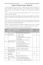
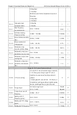
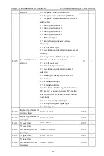
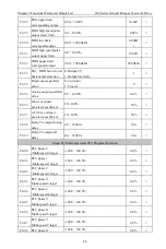
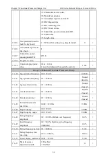
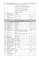
F4-15 V1 input filter factor
0
~
20(When the PID pressure is unstable,
increase appropriately; when the specified input
requires quick response, decrease appropriately)
6
√
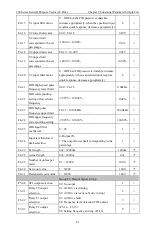
F4-16 V2 lower limit value
0.00
~
F4-18
0.10V
√
F4-17
V2 lower limit
corresponds to the set
percentage
-100.0%
~
100.0%
0.0%
√
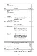
F4-18 V2 upper limit value
F4-16
~
10.00V
9.90V
√
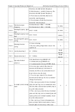
F4-19
V2 upper limit
corresponds to the set
percentage
-100.0%
~
100.0%
100.0%
√
F4-20 V2 Input filter factor
0
~
20(When PID pressure is unstable, increase
appropriately; when a specified input requires
quick response, decrease appropriately)
6
√
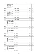
F4-21
HDI High-speed pulse
frequency lower limit
0.00
~
F4-23
0.00kHz
√
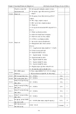
F4-22
HDI corresponding
setting of lower limit
frequency
-99.99%
~
100.00%
0.00%
√
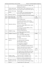
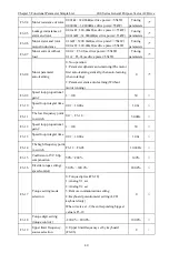
F4-23
HDI high pulse
frequency upper limit
F4-21
~
100.00kHz
20.00kHz
√
F4-24
HDI upper frequency
corresponding setting
-99.99%
~
100.00%
100.00%
√
F4-25
HDI Input filter
coefficient
0
~
20
3
√
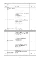
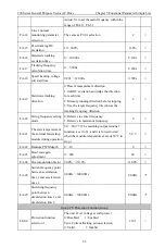
F4-26
Input less than lower
limit selection
0: Output 0%
1: The output lower limit corresponding to the
percentage
1
√
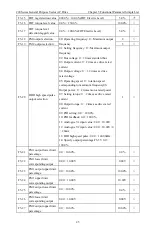
F4-27 Set
length
0m
~
32000m
1000m
√
*
F4-28 Actual
length
0m
~
3200m
0m
√
*
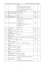
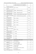
F4-29
Number of pulses per
meter
0.1
~
3200.0
100.0
√
*
F4-30 Set
count
value
1
~
32000
1000
√
*
F4-31 Designated count value 1
~
32000
1000
√
*
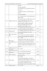
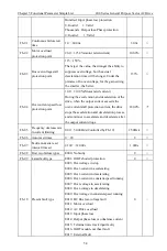
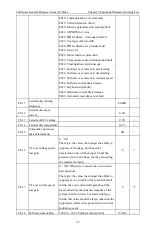
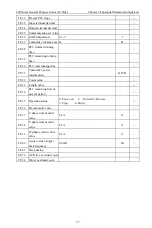
Group F5: Output Signal Group
F5-00 SP1
output
selection
00: No output
01: AC Drive is running
02: AC Drive is read( no faulty in stop)
03: AC Drive fault
04: Frequency level detection FDT output
(F5-14
、
F5-15)
05: Setting frequency arriving (F5-13)
1
√
F5-01
Relay T0 output
selection
2
√
F5-02
Relay T1 output
selection
3
√
F5-03
Relay T2 output
selection
0
√

