Chapter 8
8-15
8.5.2 Basic Sequence
0014-0314
/ / / / iR C3380i / iR C3380 / iR C2880i / iR C2880
Basic Sequence of Operation for Making 3 Prints
F-8-17
8.5.3 Identifying the Paper Size
0014-0315
/ / / / iR C3380i / iR C3380 / iR C2880i / iR C2880
The size of paper inside the cassette is detected by the cassette size dial, and is communicated to the cassette size detection PCB.
As may as 15 positions may be detected with reference to the combinations of on and off states of the array of 4 actuators mounted to the cassette size detection
PCB on the printer side and operating in conjunction with the cassette size dial.
In the absence of a cassette, all 4 actuators are off, causing the machine to assume there is no cassette.
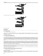
1. Size switch of AB configuration/Inch configuration
The cassette size dial is equipped with a switch operated to change between AB and Inch configurations; the cassette size detecting switch will detect the configu-
ration as soon as a cassette is fitted in the machine.
F-8-18
[1] AB/Inch switch
[2] Cassette size dial
[3] Cassette size detection PCB
2. List of paper size (AB configuration)
Print Start
Cassette 1 pickup motor
(M4)
Cassette 1 pickup
solenoid (SL2)
Cassette 1 retry sensor
(PS25)
Registration Multi Motor
(M6)
Registration Front Sensor
(PS7)
Registration clutch
(CL2)
Fixing motor
(M3)
Inner Delivery Sensor
(PS1)
Delivery Motor 1
(M14)
Delivery Sensor 1
(PS27)
*1
*3
*2
*1
pickup
*3
registration
*2
pre-registration
cassette 1 pickup motor rotation
increased
cassette 1: 3 sheets of paper
[2]
SW0
SW1
SW2
SW3
SW4
INCH
SW4-ON=INCH
[1]
[3]
Содержание iR C3380 series
Страница 1: ...Aug 29 2006 Service Manual iR C3380 2880 Series...
Страница 2: ......
Страница 6: ......
Страница 23: ...Chapter 1 Introduction...
Страница 24: ......
Страница 26: ......
Страница 52: ......
Страница 53: ...Chapter 2 Installation...
Страница 54: ......
Страница 127: ...Chapter 3 Basic Operation...
Страница 128: ......
Страница 130: ......
Страница 136: ......
Страница 137: ...Chapter 4 Main Controller...
Страница 138: ......
Страница 160: ......
Страница 161: ...Chapter 5 Original Exposure System...
Страница 162: ......
Страница 188: ...Chapter 5 5 24 F 5 68 4 Remove the original sensor 2 hook 1 F 5 69...
Страница 189: ...Chapter 6 Laser Exposure...
Страница 190: ......
Страница 192: ......
Страница 206: ......
Страница 207: ...Chapter 7 Image Formation...
Страница 208: ......
Страница 256: ......
Страница 257: ...Chapter 8 Pickup Feeding System...
Страница 258: ......
Страница 262: ......
Страница 303: ...Chapter 9 Fixing System...
Страница 304: ......
Страница 306: ......
Страница 321: ...Chapter 10 Externals and Controls...
Страница 322: ......
Страница 326: ......
Страница 336: ...Chapter 10 10 10 F 10 10 2 Remove the check mark from SNMP Status Enabled...
Страница 337: ...Chapter 10 10 11 F 10 11...
Страница 359: ...Chapter 11 MEAP...
Страница 360: ......
Страница 362: ......
Страница 401: ...Chapter 12 RDS...
Страница 402: ......
Страница 404: ......
Страница 411: ...Chapter 13 Maintenance and Inspection...
Страница 412: ......
Страница 414: ......
Страница 416: ...Chapter 13 13 2 F 13 1 8 9 1 2 3 3 5 6 7 10 11 12 13 14 4...
Страница 421: ...Chapter 14 Standards and Adjustments...
Страница 422: ......
Страница 424: ......
Страница 431: ...Chapter 15 Correcting Faulty Images...
Страница 432: ......
Страница 434: ......
Страница 459: ...Chapter 16 Self Diagnosis...
Страница 460: ......
Страница 462: ......
Страница 481: ...Chapter 17 Service Mode...
Страница 482: ......
Страница 484: ......
Страница 571: ...Chapter 18 Upgrading...
Страница 572: ......
Страница 574: ......
Страница 603: ...Chapter 19 Service Tools...
Страница 604: ......
Страница 605: ...Contents Contents 19 1 Service Tools 19 1 19 1 1 Special Tools 19 1 19 1 2 Solvents and Oils 19 2...
Страница 606: ......
Страница 609: ...Aug 29 2006...
Страница 610: ......


