Chapter 8
8-22
8.7.4 Material Difference Jam Detection
0014-3046
/ / / / iR C3380i / iR C3380 / iR C2880i / iR C2880
The machine determines the following cases as the material difference jam, and stop its operation.
- In case the material is non-transparency when transparency is set.
- In case the material is transparency when material other than transparency is set.
In this machine, one transparency sensor is used for material difference detection. The transparency sensor is allocated at the almost same position of the pre-reg-
istration sensor (a point where 21.5 mm upstream from the registration roller) on the feeding path. (In addition, the pre-registration sensor is allocated at the point
where 19.9 mm upstream from the registration roller.) The transparency sensor is comprised of 2 PCBs of LED; the light emission area (UN18) and the light re-
ception area (UN19).
In this machine, the material difference is detected according to the transmittance of material being fed. The transmittance of material is calculated according to the
sensor output (reference value A) under the condition that no shielding material presents at the transparency sensor, and the sensor output (measured value B) under
the condition that a fed material presents.
1. Reading the Reference Value
The reading of the reference value is executed at the following timing:
- After warm-up rotation when turning the power on.
- After warm-up rotation after opening/closing the right door.
The prism facing to the transparency sensor is allocated at the right door side. Because the detected voltage changes by opening/closing the right door, the reference
value must be measured after opening/closing it. Measurement method of the reference value is as follow:
1) Turn ON the LED of transparency sensor, and read the sensor output 3 times with constant interval (every 16 ms).
2) Among the read values, save the smallest value as the reference value A (the 3 read values fall somewhere into the predetermined range).
3) Turn OFF the LED and finish the measurement.
2. Reading the Measured Value
Start to read the transparency sensor when a paper is fed from a source of paper to the registration roller and the pre-registration sensor turns ON.
1) Turn ON the LED of transparency sensor, and read the sensor output 3 times with constant interval (every 16 ms).
2) Among the read values, save the largest value as the measured value B.
3) Turn OFF the LED and finish the measurement.
4) Based on the reference value A and the measured value B, calculate the transmittance of material. If the transmittance is the predetermined value (=45%) or
above, the detected material is judged as a transparency. If the result is less than the predetermined value, the material is judged as non-transparency (e.g., plain
paper, heavy paper, color paper, tracing paper).
If the result of the step 4 indicates that the material is non-transparency while transparency is set and vice versa, the machine considers as a jam due to the material
difference, and stops the machine. (Jam code: 0D93)
Reference:
The detection is not designed to protect a transparency for CLC (a transparency with a white mark on the leading edge) from being fixed in order to avoid the
occurrence of symptoms that cause damage on the fixing assembly or error codes when it is used.
In this machine, a transparency for CLC might be wrapped around the fixing assembly when using it, and it causes the fixing inside delivery delay jam (0107 jam).
When the fixing motor is stopped because of a jam detection processing, a transparency is not completely wrapped around the fixing roller. By executing the jam
processing from the upstream of feeding as a jam processing flow, it prevents the sheet to be wrapped around the fixing assembly. Therefore, the control detecting
a transparency for CLC and stopping print is not executed.
8.8 Pre-Fixing Feeding
8.8.1 Fixing Arch Control
0014-3187
/ / / / iR C3380i / iR C3380 / iR C2880i / iR C2880
1. Fixing Arch Control
This is the control performed between the secondary transfer unit and the fixing unit. The perimeter of the roller increases due to heat expansion on the pressure
roller of the fixing unit. Therefore, the paper feeding speed on the fixing side becomes faster than the one for secondary transfer at constant rotation speed. This
causes papers to be pulled towards the fixing side. When making the speed on the fixing side lower than the one for secondary transfer to make larger arch of paper,
papers are pushed into the fixing side from the secondary transfer side. Too large and small arch of papers affects the image. To feed papers to the fixing unit at
optimum status, this control system monitors the arch of papers and changes the feeding speed due to according its status.
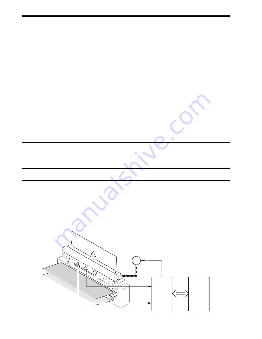
2. Control Mechanism
The sensors and motors regarding the fixing arch control are shown as below.
F-8-26
DC Driver
DCON
PS16
PS2
M3
FUSE_M_XA
FUSE_M_A
FUSE_M_B
FUSE_M_XB
LOOP_SNS
LOOP2_SNS
Содержание iR C3380 series
Страница 1: ...Aug 29 2006 Service Manual iR C3380 2880 Series...
Страница 2: ......
Страница 6: ......
Страница 23: ...Chapter 1 Introduction...
Страница 24: ......
Страница 26: ......
Страница 52: ......
Страница 53: ...Chapter 2 Installation...
Страница 54: ......
Страница 127: ...Chapter 3 Basic Operation...
Страница 128: ......
Страница 130: ......
Страница 136: ......
Страница 137: ...Chapter 4 Main Controller...
Страница 138: ......
Страница 160: ......
Страница 161: ...Chapter 5 Original Exposure System...
Страница 162: ......
Страница 188: ...Chapter 5 5 24 F 5 68 4 Remove the original sensor 2 hook 1 F 5 69...
Страница 189: ...Chapter 6 Laser Exposure...
Страница 190: ......
Страница 192: ......
Страница 206: ......
Страница 207: ...Chapter 7 Image Formation...
Страница 208: ......
Страница 256: ......
Страница 257: ...Chapter 8 Pickup Feeding System...
Страница 258: ......
Страница 262: ......
Страница 303: ...Chapter 9 Fixing System...
Страница 304: ......
Страница 306: ......
Страница 321: ...Chapter 10 Externals and Controls...
Страница 322: ......
Страница 326: ......
Страница 336: ...Chapter 10 10 10 F 10 10 2 Remove the check mark from SNMP Status Enabled...
Страница 337: ...Chapter 10 10 11 F 10 11...
Страница 359: ...Chapter 11 MEAP...
Страница 360: ......
Страница 362: ......
Страница 401: ...Chapter 12 RDS...
Страница 402: ......
Страница 404: ......
Страница 411: ...Chapter 13 Maintenance and Inspection...
Страница 412: ......
Страница 414: ......
Страница 416: ...Chapter 13 13 2 F 13 1 8 9 1 2 3 3 5 6 7 10 11 12 13 14 4...
Страница 421: ...Chapter 14 Standards and Adjustments...
Страница 422: ......
Страница 424: ......
Страница 431: ...Chapter 15 Correcting Faulty Images...
Страница 432: ......
Страница 434: ......
Страница 459: ...Chapter 16 Self Diagnosis...
Страница 460: ......
Страница 462: ......
Страница 481: ...Chapter 17 Service Mode...
Страница 482: ......
Страница 484: ......
Страница 571: ...Chapter 18 Upgrading...
Страница 572: ......
Страница 574: ......
Страница 603: ...Chapter 19 Service Tools...
Страница 604: ......
Страница 605: ...Contents Contents 19 1 Service Tools 19 1 19 1 1 Special Tools 19 1 19 1 2 Solvents and Oils 19 2...
Страница 606: ......
Страница 609: ...Aug 29 2006...
Страница 610: ......


