Chapter 2
2-19
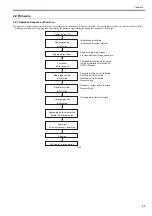
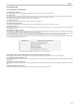
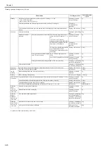
Details of the cleaning function are shown in the table below.
Cleaning mode
Name of Service mode or
PRINT INF
(Name of Main Menu)
Operation
Description of cleaning
Cleaning 1
CLN-A-1/CLN-M-1
(Head Cleaning A)
Normal cleaning
Removes dried ink from nozzles, thick ink accumulated on the
face, and paper particles.
Cleaning 2
CLN-A-2
Ink level adjustment and cleaning
Adjust the ink level in the head by suction, and then performs
normal cleaning.
Cleaning 3
CLN-A-3
Initial filling ink
Fills the empty tube (during initial installation) with ink, and
then performs normal cleaning.
Cleaning 4
CLN-M-4
(Replace P.head)
Ink drainage for head replacement
Drains ink to replace the head (drains only the ink in the head).
Cleaning 5
CLN-M-5
(Move Printer)
Ink drainage for secondary transport
Drains ink from the head and tube for secondary transport.
Cleaning 6
CLN-A-6/CLN-M-6
(Head Cleaning B)
Normal (strong) cleaning
Performs suction stronger than when adjusting the ink filling
amount in the head or normal cleaning to unclog nozzles.
Cleaning 7
CLN-A-7
Aging
Performs idle ejection after replacement of the head.
Cleaning 10
CLN-A-10
(Move Printer)
Ink filling after secondary transport
Fills the empty tube (during installation after secondary
transport) with ink, and performs normal cleaning.
Cleaning 11
CLN-A-11
Ink filling after head replacement
Performs normal cleaning after head replacement and ink
filling.
Cleaning 15
CLN-A-15
Dot count suction
Performs suction to remove ink adhered to dried nozzles and
thick ink accumulated on the face when the dot count reaches
the prescribed value.
Cleaning 16
CLN-A-16
Precipitated ink agitation
Performs the agitation (ink supply valve open/close) operation
to prevent the ink ingredient from precipitating.
Cleaning 17
CLN-A-17
Cleaning (weak)
Performs cleaning weaker than normal cleaning to unclog
nozzles.
Содержание image Prograf iPF780 Series
Страница 1: ...Mar 27 2014 Service Manual iPF780 760 750 series iPF785...
Страница 9: ...Chapter 1 PRODUCT DESCRIPTION...
Страница 57: ...Chapter 2 TECHNICAL REFERENCE...
Страница 117: ...Chapter 3 INSTALLATION...
Страница 125: ...Chapter 4 DISASSEMBLY REASSEMBLY...
Страница 133: ...Chapter 4 4 7 3 Remove one screw 1 release two hooks 2 and then remove the output guide middle left 3 F 4 11 1 3 2 2...
Страница 175: ...Chapter 4 4 49 2 Shaft Cleaner 1 F 4 97 1 1...
Страница 176: ...Chapter 4 4 50 3 Upper Cover Hinge Catch 1 Roll Cover Slide Guide 2 F 4 98 2 1...
Страница 179: ...Chapter 5 MAINTENANCE...
Страница 186: ...Chapter 6 TROUBLESHOOTING...
Страница 212: ...Chapter 7 SERVICE MODE...
Страница 267: ...Mar 19 2014 PARTS CATALOG iPF786 785 781 780 765 760 755 750...
Страница 275: ...STAND UNIT ST 33 STAND UNIT ST 34 100V Q51 1767 000 230 KOR Q51 1768 000 Q51 2560 000 Q51 2800 000...
Страница 299: ...2 23 FIGURE 09 CUTTER UNIT J12 J7 J11 J31 J34 J33 A A 10 8 1 502 7 5 13 13 9 11 8 501 6 12 2 3 4 14 14 14 15 503...
Страница 301: ...2 25 FIGURE 10 PLATEN GUIDE UNIT 1 3 6 2 8 4 5 10 10 10 9 9 11...
Страница 326: ......

