Chapter 6
6-1
6.1 Troubleshooting
6.1.1 Outline
6.1.1.1 Outline of Troubleshooting
0013-1940
1. Outline
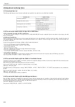
Troubles subject to troubleshooting are classified into those shown on the display (warning, error, and service call) and those not shown on the display.
The code of warning and error is shown by combining alphanumeric characters of eight digits and four digits.
The code of service call error is shown by the initial character of "E" and combining alphanumeric characters of three digits and four digits.
No code number is displayed when a warning occurs. Selecting [SERVICE MODE] > [DISPLAY] > [WARNING] in service mode allows you to check the warning
log.
2. Precautions for Troubleshooting
1) Check the environmental conditions and the media used for printing.
2) Before performing troubleshooting, make sure that all connectors and cables are connected properly.
3) When servicing the printer with the external cover removed and the AC power supplied, be extremely careful to avoid electric shock and shorting electrical
devices.
4) In the following sections, the troubleshooting steps are described such that the component related to the most probable cause of the problem will be repaired or
replaced first, being followed by components with less problem probability. If multiple components have the same problem probability, the steps are described
beginning with the easiest one.
After performing each step, check to see if the problem has been resolved by making test prints. If the problem persists, proceed to the next step.
5) After completion of the troubleshooting, check that all connectors and cables have been reconnected and screws have been tightened firmly.
6) Whenever you have performed replacement or repair services, make test prints to check whether the problem has been resolved.
7) When connecting with the printer by using the LAN cable at the service working, be sure to enter the service mode to recognize the printer correctly.
6.2 Error Code
6.2.1 Outline
6.2.1.1 Outline
0031-2603
The printer indicates errors using the display and LEDs.
If an error occurs during printing, the printer status is also displayed on the status monitor of the printer driver.
The following three types of errors are displayed on the display:
- Warning
Status where the print operation can be continued without remedying the cause of the problem. This can, however, adversely affect the printing results.
- Error
Status where the print operation is stopped, and the regular operation cannot be recovered until the cause of the problem is remedied.
- Service call error
When a service call error occurs, the error is not cleared and the error indication remains on the operation panel even if the printer is powered off and on again.
(Occurrence of the service call error is indicated again at power-on.)
This measure is taken to prevent user's recovery of the service call error and damages to the printer.
Service call errors can be cleared, however, by starting up the printer in the service mode.
Note that some of the warnings, errors, and service call error described in the following tables may not appear in this printer.
In addition, the message that appears on the screen may not be the same as what is described in the table.
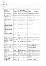
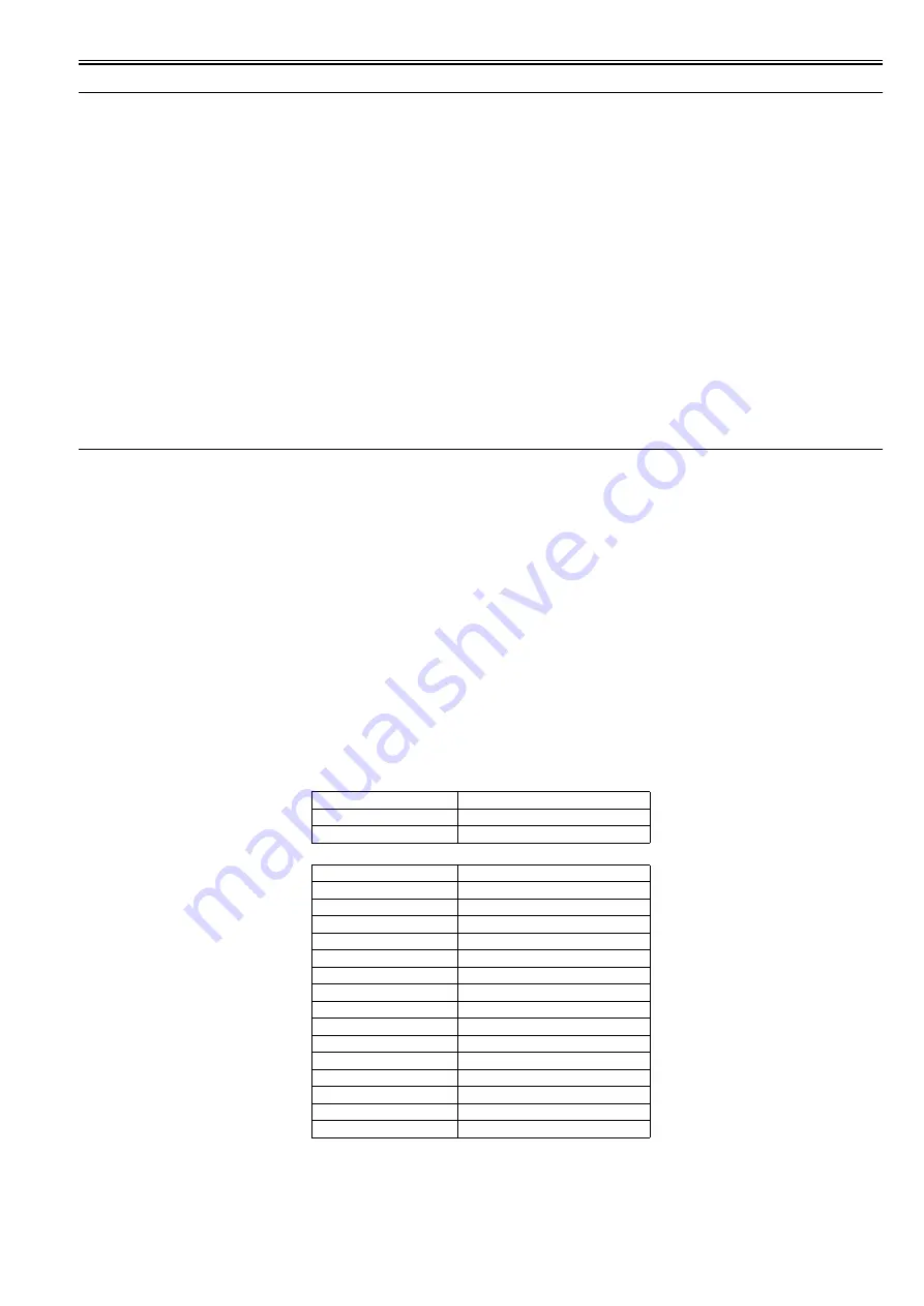
The first 4 digits of Warning and Error code show the following description.
The first 2 digits of code
Description
01xxxxxx-xxx
Warning
03xxxxxx-xxx
Error
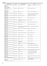
The next 2 digits of code
Description
xx01xxxx-xxxx
Jam-related
xx03xxxx-xxxx
Cover-related
xx06xxxx-xxxx
Media-related
xx13xxxx-xxxx
Controller-related
xx1Axxxx-xxxx
HDD-related
xx32xxxx-xxxx
Media-related
xx34xxxx-xxxx
PDL-related
xx80xxxx-xxxx
Printhead-related
xx81xxxx-xxxx
Inktank-related
xx83xxxx-xxxx
Inktank-related
xx84xxxx-xxxx
Maintenance cartridge-related
xx86xxxx-xxxx
Print-related
xx87xxxx-xxxx
Cutter-related
xx89xxxx-xxxx
Media take-up unit-related
xx90xxxx-xxxx
Version up-related
Содержание image Prograf iPF780 Series
Страница 1: ...Mar 27 2014 Service Manual iPF780 760 750 series iPF785...
Страница 9: ...Chapter 1 PRODUCT DESCRIPTION...
Страница 57: ...Chapter 2 TECHNICAL REFERENCE...
Страница 117: ...Chapter 3 INSTALLATION...
Страница 125: ...Chapter 4 DISASSEMBLY REASSEMBLY...
Страница 133: ...Chapter 4 4 7 3 Remove one screw 1 release two hooks 2 and then remove the output guide middle left 3 F 4 11 1 3 2 2...
Страница 175: ...Chapter 4 4 49 2 Shaft Cleaner 1 F 4 97 1 1...
Страница 176: ...Chapter 4 4 50 3 Upper Cover Hinge Catch 1 Roll Cover Slide Guide 2 F 4 98 2 1...
Страница 179: ...Chapter 5 MAINTENANCE...
Страница 186: ...Chapter 6 TROUBLESHOOTING...
Страница 212: ...Chapter 7 SERVICE MODE...
Страница 267: ...Mar 19 2014 PARTS CATALOG iPF786 785 781 780 765 760 755 750...
Страница 275: ...STAND UNIT ST 33 STAND UNIT ST 34 100V Q51 1767 000 230 KOR Q51 1768 000 Q51 2560 000 Q51 2800 000...
Страница 299: ...2 23 FIGURE 09 CUTTER UNIT J12 J7 J11 J31 J34 J33 A A 10 8 1 502 7 5 13 13 9 11 8 501 6 12 2 3 4 14 14 14 15 503...
Страница 301: ...2 25 FIGURE 10 PLATEN GUIDE UNIT 1 3 6 2 8 4 5 10 10 10 9 9 11...
Страница 326: ......

