Chapter 7
7-20
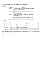
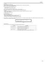
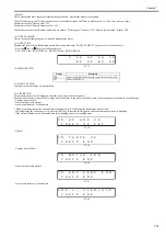
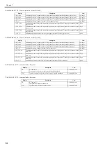
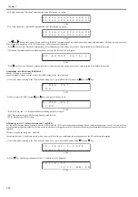
15) HEAD CHK
Perform in case the printhead is abnormal. It can guess whether the failure cause is the printhead or not.
MEMO:
As the printhead and thermistor are high temperature after printing immediately, perform this mode after 5 minutes or more printing is completed.
Display the value (analogue) detected by the printhead, the thermistor on the carriage PCB, DI sensor (Di0/Di1) and head Vh.
Check whether the detection value is normal or not to judge the abnormal part.
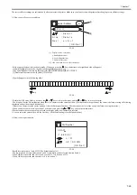
Press the
/
key to select the item, and then press the
key to display the detection value.
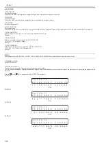
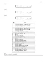
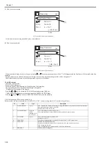
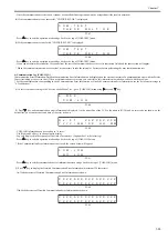
- temp
F-7-23
- AD Di0
F-7-24
- AD Di1
F-7-25
- AD Vh
F-7-26
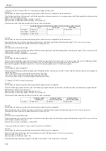
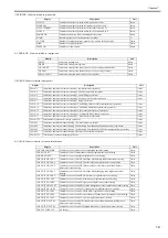
<CHECK>
Judge the failure part by comparing the temperature of the printhead and the value detected by thermistor on the carriage PCB.
T-7-1
*: Adequate temperature ranges when the surrounding temperature (temperature/humidity sensor detection value) of the printer is 25 degrees centigrade. For ex-
ample, when the surrounding temperature is 30 degrees centigrade, above temperatures rise each 5 degrees centigrade.
e) REPLACE
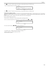
1) CUTTER
This mode is for replacing the cutter.
f) COUNTER
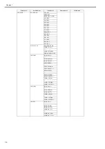
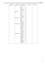
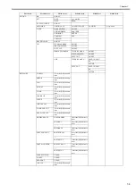
Displays the life (operation frequency and time) of each unit, print counts for each media type, and else.
The count values can be printed from [PRINT INF].
PrintHead temperature
(Centigrade degree)*
Thermistor temperature
(Centigrade degree)*
Judgement
22 to 28
22 to 28
Normal
21 or less, 29 or more
The part except for the printhead may have a failure.
(Carriage PCB, flexible cable, main controller PCB)
21 or less, 29 or more
22 to 28
The printhead may have a failure.
21 or less, 29 or more
The printhead or the carriage PCB or the flexible cable
or the main controller PCB may have a failure.
-
1 5
2 5
7
t
2 8
2 5
1 2 6
7
T
3 0
-
2
1 2
Printhead temperature
(centigrade degrees)
chipA chipB chipC
chipD chipE chipF
T: Thermistor detection temperature
mounted on the Carriage PCB
(centigrade degrees)
t: Temperature/Humidity detection sensor
detection temperature
(centigrade degrees)
1 0 2 3
6
1 2 7
0
2 5 5
1 2
1 0 2 3
D
7
3
Head DI sensor (Di0) detection analogue value
1 0 2 3
6
1 2 7
1
2 5 5
1 2
1 0 2 3
D
7
3
Head DI sensor (Di1) detection analogue value
h
1 0 2 3
V
Head VH detection analogue value
Содержание image Prograf iPF780 Series
Страница 1: ...Mar 27 2014 Service Manual iPF780 760 750 series iPF785...
Страница 9: ...Chapter 1 PRODUCT DESCRIPTION...
Страница 57: ...Chapter 2 TECHNICAL REFERENCE...
Страница 117: ...Chapter 3 INSTALLATION...
Страница 125: ...Chapter 4 DISASSEMBLY REASSEMBLY...
Страница 133: ...Chapter 4 4 7 3 Remove one screw 1 release two hooks 2 and then remove the output guide middle left 3 F 4 11 1 3 2 2...
Страница 175: ...Chapter 4 4 49 2 Shaft Cleaner 1 F 4 97 1 1...
Страница 176: ...Chapter 4 4 50 3 Upper Cover Hinge Catch 1 Roll Cover Slide Guide 2 F 4 98 2 1...
Страница 179: ...Chapter 5 MAINTENANCE...
Страница 186: ...Chapter 6 TROUBLESHOOTING...
Страница 212: ...Chapter 7 SERVICE MODE...
Страница 267: ...Mar 19 2014 PARTS CATALOG iPF786 785 781 780 765 760 755 750...
Страница 275: ...STAND UNIT ST 33 STAND UNIT ST 34 100V Q51 1767 000 230 KOR Q51 1768 000 Q51 2560 000 Q51 2800 000...
Страница 299: ...2 23 FIGURE 09 CUTTER UNIT J12 J7 J11 J31 J34 J33 A A 10 8 1 502 7 5 13 13 9 11 8 501 6 12 2 3 4 14 14 14 15 503...
Страница 301: ...2 25 FIGURE 10 PLATEN GUIDE UNIT 1 3 6 2 8 4 5 10 10 10 9 9 11...
Страница 326: ......

