Chapter 7
7-13
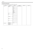
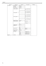
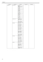
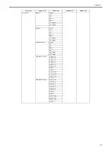
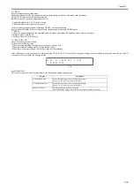
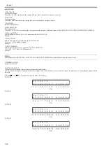
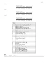
Screen 1, Screen 2 and Screen 3 are selectable with the
and
keys.
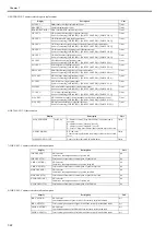
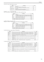
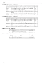
These screens display the associated sensor status as listed in the table below.
Display position
Sensor name
LCD display contents
1
Pump cam sensor
0:Sensor ON, 1:Sensor OFF
2
Ink supply valve open/closed detection sensor (R)
0:Sensor OFF, 1:Sensor ON
3
(Not Used)
-
4
(Not Used)
-
5
(Not Used)
-
6
Lift cam sensor
0:Sensor ON, 1:Sensor OFF
7
Feed roller HP sensor
0:Sensor ON, 1:Sensor OFF
8
Upper cover lock switch
0:Cover close, 1:Cover open
9
(Not Used)
0:Cover open, 1:Cover close
10
Ink tank cover switch (R)
0:Cover open, 1:Cover close
11
Ink tank cover switch (L)
0:Cover open, 1:Cover close
12
(Not Used)
-
13
(Not Used)
-
14
(Not Used)
-
15
(Not Used)
-
16
(Not Used)
-
17
(Not Used)
-
18
(Not Used)
-
19
(Not Used)
-
20
Cutter HP sensor
0:Sensor ON, 1:Sensor OFF
21
Cutter left position sensor
0:Sensor ON, 1:Sensor OFF
22
Carriage HP sensor
0:Sensor ON, 1:Sensor OFF
23
(Not Used)
-
24
Paper detection sensor
0:Media loaded, 1:No media
25
(Not Used)
-
26
(Not Used)
-
27
(Not Used)
-
28
(Not Used)
-
29
(Not Used)
-
30
Ink supply valve open/closed detection sensor (L)
0:Sensor OFF, 1:Sensor ON
31
(Not Used)
-
32
(Not Used)
-
33
Release lever lock sensor
0:Sensor ON, 1:Sensor OFF
34
Pinch roller pressure release switch
0:Realeased, 1:Pressured
35
Shutter HP sensor
0:Sensor OFF, 1:Sensor ON
36
(Not Used)
-
37
(Not Used)
-
38
(Not Used)
-
39
(Not Used)
-
40
(Not Used)
-
41
Flexible cable connection detection (J3601 pin no.50) 0:Connect, 1:Disconnect
42
Flexible cable connection detection (J3601 pin no.1) 0:Connect, 1:Disconnect
43
Flexible cable connection detection (J3602 pin no.50) 0:Connect, 1:Disconnect
44
Flexible cable connection detection (J3602 pin no.1) 0:Connect, 1:Disconnect
45
(Not Used)
-
46
(Not Used)
-
47
(Not Used)
-
48
(Not Used)
-
Содержание image Prograf iPF780 Series
Страница 1: ...Mar 27 2014 Service Manual iPF780 760 750 series iPF785...
Страница 9: ...Chapter 1 PRODUCT DESCRIPTION...
Страница 57: ...Chapter 2 TECHNICAL REFERENCE...
Страница 117: ...Chapter 3 INSTALLATION...
Страница 125: ...Chapter 4 DISASSEMBLY REASSEMBLY...
Страница 133: ...Chapter 4 4 7 3 Remove one screw 1 release two hooks 2 and then remove the output guide middle left 3 F 4 11 1 3 2 2...
Страница 175: ...Chapter 4 4 49 2 Shaft Cleaner 1 F 4 97 1 1...
Страница 176: ...Chapter 4 4 50 3 Upper Cover Hinge Catch 1 Roll Cover Slide Guide 2 F 4 98 2 1...
Страница 179: ...Chapter 5 MAINTENANCE...
Страница 186: ...Chapter 6 TROUBLESHOOTING...
Страница 212: ...Chapter 7 SERVICE MODE...
Страница 267: ...Mar 19 2014 PARTS CATALOG iPF786 785 781 780 765 760 755 750...
Страница 275: ...STAND UNIT ST 33 STAND UNIT ST 34 100V Q51 1767 000 230 KOR Q51 1768 000 Q51 2560 000 Q51 2800 000...
Страница 299: ...2 23 FIGURE 09 CUTTER UNIT J12 J7 J11 J31 J34 J33 A A 10 8 1 502 7 5 13 13 9 11 8 501 6 12 2 3 4 14 14 14 15 503...
Страница 301: ...2 25 FIGURE 10 PLATEN GUIDE UNIT 1 3 6 2 8 4 5 10 10 10 9 9 11...
Страница 326: ......

