Chapter 3
3-5
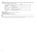
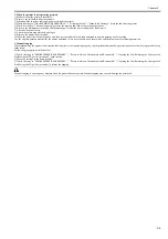
2. When the printer is not operating properly
1) Make sure that the printer is turned off.
2) Remove the roll holder from the roll unit.
3) Disconnect the interface cable and power cord from the printer.
4) While referring to "DISASSEMBLY/REASSEMBLY" > "Draining the Ink" > "Manual Ink Drainage", drain the ink from the printer.
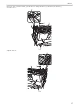
5) While referring to "3. Manual capping", perform the capping and lock of the carriage operations.
6) Remove the maintenance cartridge, and then package it so that the waste ink does not leak from it.
7) Attach all external covers.
8) Attach the cushioning materials and tapes.
9) Remove the printer from the stand.
10) Pack the printer into the packing box, and then put the roll media, ink tank and stand in another packing box for moving.
Use the original packing material for the printer and stand. If it is not available, pack them with a sufficient amount of cushioning materials.
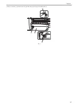
3. Manual capping
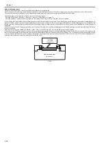
When transporting the printer at the situation that the printer is not operating properly, cap the printhead manually to protect the nozzles from drying out and to keep
them clean.
Follow the procedures described below:
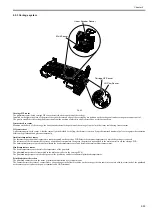
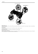
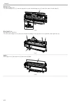
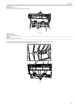
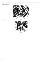
1) While referring to "DISASSEMBLY/REASSEMBLY" > "Points to Note on Disassembly and Reassembly" > "Opening the Cap/Releasing the Carriage Lock
Pin/Moving the Wiper Unit manually", open the cap.
2) Move the carriage to the home position.
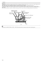
3) While referring to "DISASSEMBLY/REASSEMBLY" > "Points to Note on Disassembly and Reassembly" > "Opening the Cap/Releasing the Carriage Lock
Pin/Moving the Wiper Unit manually", perform the capping.
Manual capping is an emergency measure when the printer does not operate. Manual capping may cause to damage the printhead.
Содержание image Prograf iPF780 Series
Страница 1: ...Mar 27 2014 Service Manual iPF780 760 750 series iPF785...
Страница 9: ...Chapter 1 PRODUCT DESCRIPTION...
Страница 57: ...Chapter 2 TECHNICAL REFERENCE...
Страница 117: ...Chapter 3 INSTALLATION...
Страница 125: ...Chapter 4 DISASSEMBLY REASSEMBLY...
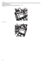
Страница 133: ...Chapter 4 4 7 3 Remove one screw 1 release two hooks 2 and then remove the output guide middle left 3 F 4 11 1 3 2 2...
Страница 175: ...Chapter 4 4 49 2 Shaft Cleaner 1 F 4 97 1 1...
Страница 176: ...Chapter 4 4 50 3 Upper Cover Hinge Catch 1 Roll Cover Slide Guide 2 F 4 98 2 1...
Страница 179: ...Chapter 5 MAINTENANCE...
Страница 186: ...Chapter 6 TROUBLESHOOTING...
Страница 212: ...Chapter 7 SERVICE MODE...
Страница 267: ...Mar 19 2014 PARTS CATALOG iPF786 785 781 780 765 760 755 750...
Страница 275: ...STAND UNIT ST 33 STAND UNIT ST 34 100V Q51 1767 000 230 KOR Q51 1768 000 Q51 2560 000 Q51 2800 000...
Страница 299: ...2 23 FIGURE 09 CUTTER UNIT J12 J7 J11 J31 J34 J33 A A 10 8 1 502 7 5 13 13 9 11 8 501 6 12 2 3 4 14 14 14 15 503...
Страница 301: ...2 25 FIGURE 10 PLATEN GUIDE UNIT 1 3 6 2 8 4 5 10 10 10 9 9 11...
Страница 326: ......


