Chapter 7
7-15
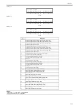
6) CR REG
Executes automatic head adjustment.
Make this adjustment if the resistration remains partially misregistered after user-mode head adjustment.
EXECUTE: Execute automatic head adjustment.
RESET: Reset the resistration adjustment value (0).
- Applicable media size is A2 (17inch) or larger.
- Applicable media type is photo glossy paper
If an error message appears when performing CR REG, check the following.
Replace the multi sensor if the error reoccurs after checking and performing CR REG again.
<CHECK>
1. Check for non-discharging of the printhead and dirty media, and replace the printhead and/or media if necessary.
2. Perform [Head Cleaning A].
3. Perform [Head Posi. Adj.]-[Auto].
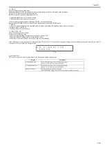
7) CR MOTOR COG
Adjust the carriage motor rotation.
Perform in the following cases:
- When removing/attaching or replacing the carriage or carriage belt.
- When replacing the carriage motor or linear encoder sensor.
- When there is excessive load on the carriage (such as when jamming)
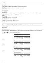
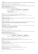
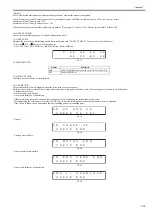
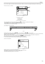
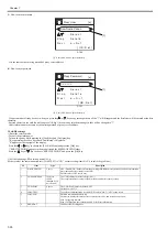
If the following error message appears when performing CR MOTOR COG, check that carriage and carriage belt are installed properly and clean the rail shaft. If
the error still occurs, replace the carriage motor.
F-7-9
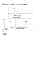
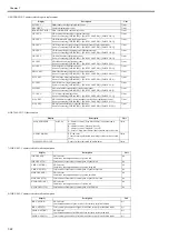
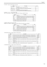
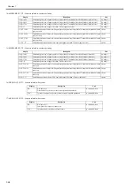
8) MARGIN ADJ
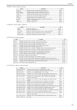
This mode is to perform the fine adjustment of the leading and trailing edge margin.
Display
Description
TOP MARGIN ADJ
Set the fine adjustment value of leading edge margin.
Range: -5.0 to 5.0mm (in 0.1mm increments)
BTM MARGIN ADJ
Set the fine adjustment value of trailing edge margin.
Range: -5.0 to 5.0mm (in 0.1mm increments)
PRINT PATTERN
Print the pattern for checking the margin.
After adjusting the margin, make sure of the margin by printing the pattern.
E R R O R
C R
V
I
B R A T
I
O N
Содержание image Prograf iPF780 Series
Страница 1: ...Mar 27 2014 Service Manual iPF780 760 750 series iPF785...
Страница 9: ...Chapter 1 PRODUCT DESCRIPTION...
Страница 57: ...Chapter 2 TECHNICAL REFERENCE...
Страница 117: ...Chapter 3 INSTALLATION...
Страница 125: ...Chapter 4 DISASSEMBLY REASSEMBLY...
Страница 133: ...Chapter 4 4 7 3 Remove one screw 1 release two hooks 2 and then remove the output guide middle left 3 F 4 11 1 3 2 2...
Страница 175: ...Chapter 4 4 49 2 Shaft Cleaner 1 F 4 97 1 1...
Страница 176: ...Chapter 4 4 50 3 Upper Cover Hinge Catch 1 Roll Cover Slide Guide 2 F 4 98 2 1...
Страница 179: ...Chapter 5 MAINTENANCE...
Страница 186: ...Chapter 6 TROUBLESHOOTING...
Страница 212: ...Chapter 7 SERVICE MODE...
Страница 267: ...Mar 19 2014 PARTS CATALOG iPF786 785 781 780 765 760 755 750...
Страница 275: ...STAND UNIT ST 33 STAND UNIT ST 34 100V Q51 1767 000 230 KOR Q51 1768 000 Q51 2560 000 Q51 2800 000...
Страница 299: ...2 23 FIGURE 09 CUTTER UNIT J12 J7 J11 J31 J34 J33 A A 10 8 1 502 7 5 13 13 9 11 8 501 6 12 2 3 4 14 14 14 15 503...
Страница 301: ...2 25 FIGURE 10 PLATEN GUIDE UNIT 1 3 6 2 8 4 5 10 10 10 9 9 11...
Страница 326: ......


