Chapter 2
2-52
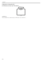
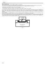
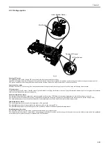
Head management sensor
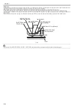
The photo-transmission-type sensor detects that the printhead is discharging ink.
The carriage moves to and stops at the detection positions for individual nozzle arrays. When the carriage is at a stop, nozzles discharge ink on after another.
The sensor detects each nozzle due to the voltage change caused when ink discharged from the nozzle blocks the sensor light.
Non-discharging nozzle detection is carried out at the following timings:
- After the execution of Cleaning 1, Cleaning 2, Cleaning 3, Cleaning 6 or Cleaning 10
- After the number of copies that has been set by the user menu choice Nozzle Check Frequency have been printed
If more than a specified number of non-discharging nozzles have been located in one session of non-discharging nozzle detection, the normal cleaning sequence is
launched before a second session of non-discharging nozzle detection is conducted. If more than a specified number of non-discharging nozzles are located in the
second session of non-discharging nozzle detection, the normal (High) cleaning session is launched before a third session of non-discharging nozzle detection is
conducted.
If there are at least 320 non-discharging nozzles out of 2560 nozzles as the result of non-discharging nozzle detection, printing is canceled after displaying a message
to replace the head.
However, if service mode: [SERVICE MODE] > [SETTING] > [HEAD DOT INF] is [ON], the following message appears.
If there are at least 30 nozzles unable to correct the non-discharging state and the number of non-discharging nozzles is less than 100 out of 2,560 nozzles as the
result of non-discharging nozzle detection, printing can continue after displaying a message to check the printing. Also, if the number of non-discharging nozzles
is at least 100 but less than 320 nozzles, printing can continue after displaying a message to check the head. And if there are at least 320 non-discharging nozzles,
printing is canceled after displaying a message to replace the head.
F-2-42
Printhead
Nozzle unit
Head management
sensor unit
Содержание image Prograf iPF780 Series
Страница 1: ...Mar 27 2014 Service Manual iPF780 760 750 series iPF785...
Страница 9: ...Chapter 1 PRODUCT DESCRIPTION...
Страница 57: ...Chapter 2 TECHNICAL REFERENCE...
Страница 117: ...Chapter 3 INSTALLATION...
Страница 125: ...Chapter 4 DISASSEMBLY REASSEMBLY...
Страница 133: ...Chapter 4 4 7 3 Remove one screw 1 release two hooks 2 and then remove the output guide middle left 3 F 4 11 1 3 2 2...
Страница 175: ...Chapter 4 4 49 2 Shaft Cleaner 1 F 4 97 1 1...
Страница 176: ...Chapter 4 4 50 3 Upper Cover Hinge Catch 1 Roll Cover Slide Guide 2 F 4 98 2 1...
Страница 179: ...Chapter 5 MAINTENANCE...
Страница 186: ...Chapter 6 TROUBLESHOOTING...
Страница 212: ...Chapter 7 SERVICE MODE...
Страница 267: ...Mar 19 2014 PARTS CATALOG iPF786 785 781 780 765 760 755 750...
Страница 275: ...STAND UNIT ST 33 STAND UNIT ST 34 100V Q51 1767 000 230 KOR Q51 1768 000 Q51 2560 000 Q51 2800 000...
Страница 299: ...2 23 FIGURE 09 CUTTER UNIT J12 J7 J11 J31 J34 J33 A A 10 8 1 502 7 5 13 13 9 11 8 501 6 12 2 3 4 14 14 14 15 503...
Страница 301: ...2 25 FIGURE 10 PLATEN GUIDE UNIT 1 3 6 2 8 4 5 10 10 10 9 9 11...
Страница 326: ......


