Chapter 2
2-51
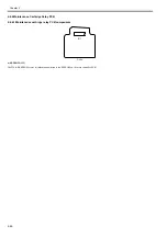
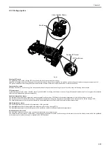
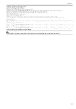
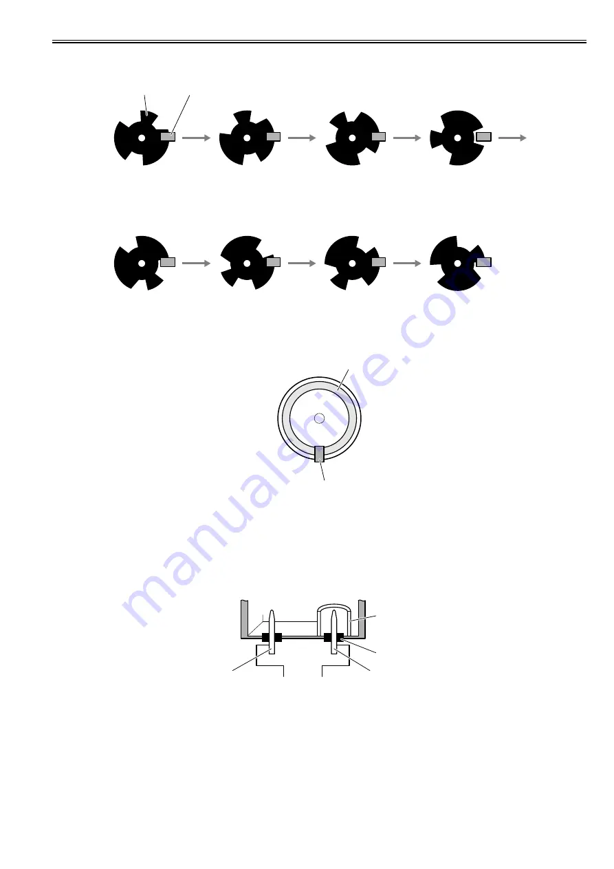
Pump cam sensor
The photo-interrupter-type pump cam sensor detects that the sensor light is shielded or unshielded by the rotary cam. The sensor detects the purge unit capping and
wiping states with the combination of the state detected by the pump cam and the state of pump motor rotation control performed by the pump encoder.
F-2-39
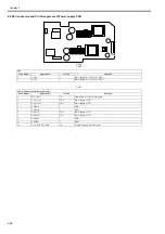
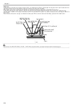
Pump encoder sensor
The pump encoder is a photo-interruptive type sensor. It reads the slits on the pump motor's encoder film to control the amount of pump motor rotation.
F-2-40
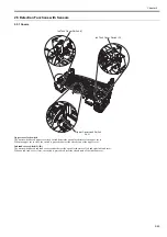
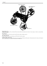
Ink supply valve open/closed detection sensor (L)/(R)
The photo-interrupter-type ink supply valve open/closed detection sensor detect the valve cam state.
When the link that operates in conjunction with the ink supply valve cam shields light, this sensor detects that the ink supply valve has been opened.
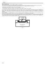
Ink detection sensor (L)/(R)
Presence of absence of ink in the ink tank is detected according to whether the two hollow needles are electrically connected.
When the ink level in the ink tank lowers below the wall around the hollow needle at the air passage, this hollow needle is electrically disconnected form the hollow
needle located on the ink supply side, thus detecting that the printer has run out of ink.
F-2-41
Shutter HP sensor
The photointerrupter-type sensor detects the presence of the cshutter at the home position.
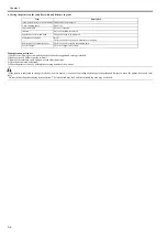
- Carriage lock
- Capping
- Suction
- Air passage valve open
- Idle suction
- Printing
- Suction during printing
- Wiping
- Carriage lock
- Air passage
- Carriage move
- Idle ejection
- Idle suction
Rotary flag
Sensor
Sensor
Slits
Ink tank
Wall
Rubber plug
Needle(air passage)
Needle (ink supply)
Содержание image Prograf iPF780 Series
Страница 1: ...Mar 27 2014 Service Manual iPF780 760 750 series iPF785...
Страница 9: ...Chapter 1 PRODUCT DESCRIPTION...
Страница 57: ...Chapter 2 TECHNICAL REFERENCE...
Страница 117: ...Chapter 3 INSTALLATION...
Страница 125: ...Chapter 4 DISASSEMBLY REASSEMBLY...
Страница 133: ...Chapter 4 4 7 3 Remove one screw 1 release two hooks 2 and then remove the output guide middle left 3 F 4 11 1 3 2 2...
Страница 175: ...Chapter 4 4 49 2 Shaft Cleaner 1 F 4 97 1 1...
Страница 176: ...Chapter 4 4 50 3 Upper Cover Hinge Catch 1 Roll Cover Slide Guide 2 F 4 98 2 1...
Страница 179: ...Chapter 5 MAINTENANCE...
Страница 186: ...Chapter 6 TROUBLESHOOTING...
Страница 212: ...Chapter 7 SERVICE MODE...
Страница 267: ...Mar 19 2014 PARTS CATALOG iPF786 785 781 780 765 760 755 750...
Страница 275: ...STAND UNIT ST 33 STAND UNIT ST 34 100V Q51 1767 000 230 KOR Q51 1768 000 Q51 2560 000 Q51 2800 000...
Страница 299: ...2 23 FIGURE 09 CUTTER UNIT J12 J7 J11 J31 J34 J33 A A 10 8 1 502 7 5 13 13 9 11 8 501 6 12 2 3 4 14 14 14 15 503...
Страница 301: ...2 25 FIGURE 10 PLATEN GUIDE UNIT 1 3 6 2 8 4 5 10 10 10 9 9 11...
Страница 326: ......


