Chapter 7
7-19
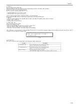
[Check 2]
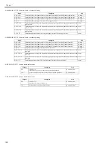
Check whether the multi sensor performance has degraded or whether the media is compatible.
When "Density gain" and "Density current value" are maximum values and "Density media output" is 168 or less, an error occurs.
Maximum value of "Density gain": 255
Maximum value of "Density current value": 245
When the multi sensor performance and media are normal, "Density gain" is about 5-100; "Density current value" is about 200.
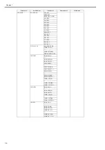
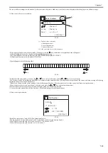
10) NOZZLE CHECK
Checks for non-discharging nozzle with head management sensor.
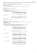
11) NOZZLE INF
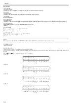
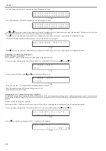
Displays the result of non-discharging nozzle check performed with "NOZZLE CHECK" by nozzle row of each ink color.
- Press the
key or
key to switch the ink color.
- AE:A-EVEN row, AO:A-ODD row, BE:B-EVEN row, BO:B-ODD row
F-7-17
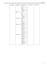
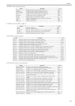
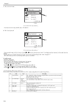
12) MEMORY CHK
13) HEAD CNT CHK
Confirms the contact status of the printhead.
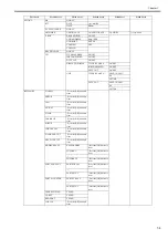
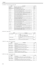
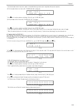
14) CR ERR CHK
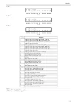
This mode performs the self diagnosis about the drive state of the carriage unit.
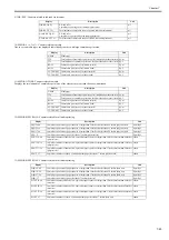
Perform in case the drive state of the carriage unit is abnormal. it can guess the failure cause of the carriage unit as shown in the followings.
- Carriage motor failure
- Linear encoder sensor failure
- Linear scale failure or overload state
* When performing this mode, open and close the upper cover by following the instructions on the screen.
After displaying the following screen, press the [OK] key to start the self diagnosis, and then the diagnosis result is displayed.
If the failure is found, check and replace the corresponding parts or surrounding parts.
F-7-18
- Normal
F-7-19
- Carriage motor failure
F-7-20
- Linear encoder sensor failure
F-7-21
- Linear scale failure or overload state
F-7-22
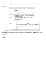
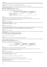
Display
Description
DDR
Checks the DDR-SDRAM mounted on the Main Controller PCB.
EEP
Checks the EEPROM.
B E
:
O K
B O :
O K
C
A E
:
O K
A O :
O K
P R E S S
O
K E Y
C R
H P
S N
O K
S
K
C H E C K
E
C R
C H E C K
K
O
N D
C H E C K
E
C R
M O T O R
R R
E
N D
C H E C K
E
C R
E N C
S
S
E R R
E N
N D
C H E C K
E
E N C
o r
O
R L O A D
V E
N D
Содержание image Prograf iPF780 Series
Страница 1: ...Mar 27 2014 Service Manual iPF780 760 750 series iPF785...
Страница 9: ...Chapter 1 PRODUCT DESCRIPTION...
Страница 57: ...Chapter 2 TECHNICAL REFERENCE...
Страница 117: ...Chapter 3 INSTALLATION...
Страница 125: ...Chapter 4 DISASSEMBLY REASSEMBLY...
Страница 133: ...Chapter 4 4 7 3 Remove one screw 1 release two hooks 2 and then remove the output guide middle left 3 F 4 11 1 3 2 2...
Страница 175: ...Chapter 4 4 49 2 Shaft Cleaner 1 F 4 97 1 1...
Страница 176: ...Chapter 4 4 50 3 Upper Cover Hinge Catch 1 Roll Cover Slide Guide 2 F 4 98 2 1...
Страница 179: ...Chapter 5 MAINTENANCE...
Страница 186: ...Chapter 6 TROUBLESHOOTING...
Страница 212: ...Chapter 7 SERVICE MODE...
Страница 267: ...Mar 19 2014 PARTS CATALOG iPF786 785 781 780 765 760 755 750...
Страница 275: ...STAND UNIT ST 33 STAND UNIT ST 34 100V Q51 1767 000 230 KOR Q51 1768 000 Q51 2560 000 Q51 2800 000...
Страница 299: ...2 23 FIGURE 09 CUTTER UNIT J12 J7 J11 J31 J34 J33 A A 10 8 1 502 7 5 13 13 9 11 8 501 6 12 2 3 4 14 14 14 15 503...
Страница 301: ...2 25 FIGURE 10 PLATEN GUIDE UNIT 1 3 6 2 8 4 5 10 10 10 9 9 11...
Страница 326: ......


