Chapter 4
4-38
4.3.11 Multi Sensor
0023-3335
a) Removing the Multi Sensor
1) Unlock the carriage unit, and then move the carriage onto the platen. Refer to "Disassembly/Reassembly > Points to Note on Disassembly and Reassembly >
Opening the Cap/Moving the Wiper Unit".
2) Remove the printhead to protect it.
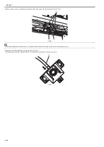
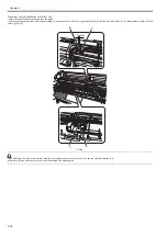
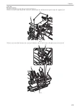
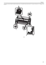
3) Remove one screw [1] and disconnect one connector [2], and then the multi sensor [3].
F-4-83
b) Removing the Multi Sensor Reference Plate
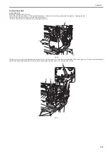
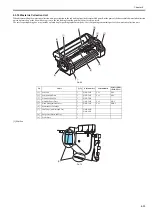
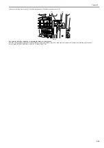
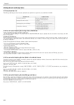
1) Remove one screw [1], and then remove the multi sensor reference plate [2].
F-4-84
Do not touch the white sheets of the multi sensor reference plate.
c) Action following the replacement of the carriage unit/multi sensor
Because the distance between the multi sensor (in the carriage unit) and the nozzles (in the printhead) is varied from one unit to another, the printer as shipped has
its optical axis corrected to adjust the image write position. When the carriage unit or multisensor has been replaced or disassembled and reassembled, they require
adjustment.
Execute service mode under the following conditions:
* The multi sensor reference plate(QL2-3160: MOUNT, MULTI SENSOR REFERENCE) must be replaced at the same time whenever the carriage or the multi
sensor is being replaced.
1) Carry out the following service mode without media loading.
- Service mode : SERVICE MODE > ADJUST > GAP CALIB.
2) Load the following media.
Media type : Photo glossy paper
Media size : Media having a width equal toor larger then that of A2-size paper
3) Carry out the following service mode.
- Service mode : SERVICE MODE > ADJUST > PRINT PATTERN > OPTICAL AXIS
[1]
[3]
[2]
[1]
[2]
Содержание image Prograf iPF780 Series
Страница 1: ...Mar 27 2014 Service Manual iPF780 760 750 series iPF785...
Страница 9: ...Chapter 1 PRODUCT DESCRIPTION...
Страница 57: ...Chapter 2 TECHNICAL REFERENCE...
Страница 117: ...Chapter 3 INSTALLATION...
Страница 125: ...Chapter 4 DISASSEMBLY REASSEMBLY...
Страница 133: ...Chapter 4 4 7 3 Remove one screw 1 release two hooks 2 and then remove the output guide middle left 3 F 4 11 1 3 2 2...
Страница 175: ...Chapter 4 4 49 2 Shaft Cleaner 1 F 4 97 1 1...
Страница 176: ...Chapter 4 4 50 3 Upper Cover Hinge Catch 1 Roll Cover Slide Guide 2 F 4 98 2 1...
Страница 179: ...Chapter 5 MAINTENANCE...
Страница 186: ...Chapter 6 TROUBLESHOOTING...
Страница 212: ...Chapter 7 SERVICE MODE...
Страница 267: ...Mar 19 2014 PARTS CATALOG iPF786 785 781 780 765 760 755 750...
Страница 275: ...STAND UNIT ST 33 STAND UNIT ST 34 100V Q51 1767 000 230 KOR Q51 1768 000 Q51 2560 000 Q51 2800 000...
Страница 299: ...2 23 FIGURE 09 CUTTER UNIT J12 J7 J11 J31 J34 J33 A A 10 8 1 502 7 5 13 13 9 11 8 501 6 12 2 3 4 14 14 14 15 503...
Страница 301: ...2 25 FIGURE 10 PLATEN GUIDE UNIT 1 3 6 2 8 4 5 10 10 10 9 9 11...
Страница 326: ......

