Chapter 2
2-53
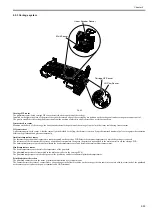
2.5.3 Carriage system
0023-2559
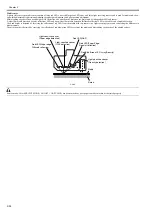
F-2-43
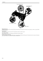
Carriage HP sensor
The photointerrupter-based carriage HP sensor detects the home position of the carriage.
Installed on the right side plate of the printer, the sensor detects an edge of the carriage home position on the carriage unit under carriage movement control.
The printer establishes the carriage home position from the position at which its edge is detected as a reference position.
Linear encoder sensor
Mounted on the back of the carriage, the linear encoder detects the position of the carriage from a slit in the linear scale during its movement.
Lift cam sensor
A photointerrupter-based sensor. After the sensor light is shielded by the flag, the lift motor is driven by a predetermined number of pulses to regulate the separation
between the printheads and platen automatically.
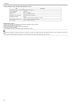
Ambient temperature sensor
The thermostat-based ambient temperature sensor mounted on the carriage PCB detects the ambient temperature to which the carriage is exposed.
The resistance of the thermistor that varies as a function of temperature changes in the printer is transmitted to the main controller via the carriage PCB.
The ambient temperature is used to help calibrate the head temperature sensor and detect abnormal ambient temperatures.
Head temperature sensor
The head temperature sensor detects the temperature of the printhead.
The printhead temperature is transmitted to the main controller via the carriage PCB.
The printhead temperature is used to help control the head drive and detect abnormal printhead temperatures.
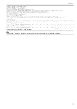
Printhead contact detection
The printhead contact detects the status of printhead installation by electrical means.
The contact detects the status of contact from voltage changes in the flexible cables on the carriage side that come into contact with two terminals of the printhead
with remote contact surfaces, the power terminals and GND terminal.
Lift Cam Sensor
Carriage HP Sensor
Multi Sensor
Linear Encoder Sensor
Содержание image Prograf iPF780 Series
Страница 1: ...Mar 27 2014 Service Manual iPF780 760 750 series iPF785...
Страница 9: ...Chapter 1 PRODUCT DESCRIPTION...
Страница 57: ...Chapter 2 TECHNICAL REFERENCE...
Страница 117: ...Chapter 3 INSTALLATION...
Страница 125: ...Chapter 4 DISASSEMBLY REASSEMBLY...
Страница 133: ...Chapter 4 4 7 3 Remove one screw 1 release two hooks 2 and then remove the output guide middle left 3 F 4 11 1 3 2 2...
Страница 175: ...Chapter 4 4 49 2 Shaft Cleaner 1 F 4 97 1 1...
Страница 176: ...Chapter 4 4 50 3 Upper Cover Hinge Catch 1 Roll Cover Slide Guide 2 F 4 98 2 1...
Страница 179: ...Chapter 5 MAINTENANCE...
Страница 186: ...Chapter 6 TROUBLESHOOTING...
Страница 212: ...Chapter 7 SERVICE MODE...
Страница 267: ...Mar 19 2014 PARTS CATALOG iPF786 785 781 780 765 760 755 750...
Страница 275: ...STAND UNIT ST 33 STAND UNIT ST 34 100V Q51 1767 000 230 KOR Q51 1768 000 Q51 2560 000 Q51 2800 000...
Страница 299: ...2 23 FIGURE 09 CUTTER UNIT J12 J7 J11 J31 J34 J33 A A 10 8 1 502 7 5 13 13 9 11 8 501 6 12 2 3 4 14 14 14 15 503...
Страница 301: ...2 25 FIGURE 10 PLATEN GUIDE UNIT 1 3 6 2 8 4 5 10 10 10 9 9 11...
Страница 326: ......


