COPYRIGHT © CANON ELECTRONICS INC. 2008 CANON DR-X10C FIRST EDITION
2-25
CHAPTER 2 FUNCTION & OPERATION
V. POWER SUPPLY
1. Power Supply
The power supply PCB of this machine
supports AC power supply input of 100 V to
240 V.
When the power switch (button) at the
front of the main body is pressed, the power
switch on the main motor PCB is turned ON.
While it is ON, 24 VDC is supplied from the
power supply PCB, the relay is turned ON,
and DC power is provided continuously.
When the power switch (button) is pressed
again, the power supply sensor is turned ON,
the relay is turned OFF and the power supply
stops.
If the “Auto USB Power Switch Setting” is
turned ON in the user mode and the USB
cable is connected, the relay is turned
ON/OFF in conjunction with the computer
power ON/OFF.
The supplied AC power is converted by a
rectifying bridge to unsmoothed power and
converted to 24 VDC power.
This DC power is supplied to each PCB
and is converted to a necessary DC voltage.
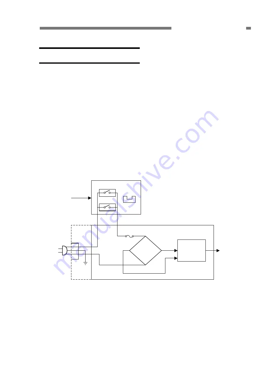
Figure 2-501 shows the block diagram of
the power supply PCB and related blocks.
AC/DC
conversion
section
Main motor PCB
Power supply PCB
Power switch
USB 5 V
Relay
Fuse
AC
power
supply
Rectifying
bridge
24 VDC
Power
supply
sensor
Figure 2-501


