Cambridge Air Solutions
58
S-Series Technical Manual
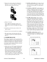
b.4.2. Provide a control signal (4-20 mA / 0-10 VDC)
to the amplifier by setting the signal level thru
the Building Automation System
OR
Remove the wires from terminals #5 and #6
of the amplifier and connect a current/voltage
signal generator to terminals #5 and #6 of the
amplifier. (Note polarity of the terminals: #5 is
negative and #6 is positive).
b.4.2. Set the modulation level to 100% (20 mA / 10
VDC).
IMPORTANT
The heater access doors must be closed for the re-
maining portion of this test.
c. Turn the burner service switch to the “LOCAL”
position. After a delay for prepurge and igniter
warm-up, the burner will light. Allow 15 seconds
for the low fire start to time out.
d. Monitor the discharge temperature until it stabi-
lizes. Do not rush through this step.
e. The discharge temperature should be 130 ± 3°F for
heaters setup for 130°F, or 160 +0/-5°F for heaters
setup for 160°F. If the discharge temperature
complies with this requirement, no calibration is
required. If the discharge temperature does not
equal the expected value, proceed to Calibration
Procedures (page 60).
f. Remove any jumpers that were installed previously.
g. When performing a start-up proceed to the next
step, otherwise perform Final Heater Preparation
(page 59).
9. GAS TRAIN LEAK CHECK
a. On EDL, EDR, EDSM, and EDSM/TP control
systems, remove the wire from terminal #3 on the
amplifier. This will drive the modulating valve to
full open.
b. Turn the blower service switch to the ”LOCAL”
position. Blower motor will start after the
motorized discharge damper opens.
c.
Turn the burner service switch to the ”LOCAL”
position. After a delay for prepurge and igniter
warm-up, the burner will light. Allow 15 seconds
for the low fire start to time out.
d. With the burner operating, spray the complete gas
train with leak detector solution, checking all pipe
connections and plugs.
m
CAUTION:
Do not allow leak detector solution to come in
contact with electrical components.
m
WARNING:
Any gas leak detected must be repaired before
unit is placed into service.
e. Turn the blower and burner service switches to the
”OFF” position.
f. Reconnect the wire to terminal #3 on the amplifier
g. When performing a start-up proceed to the next
step, otherwise perform Final Heater Preparation
(page 59).
10. GAS VALVE LEAK CHECK
All heaters should be evaluated for the gas tightness
of the gas valve seat. Heaters rated over 400,000
Btu/hr are equipped with a leak test facility to assist
in checking this seal. A momentary switch and a
gas port for measuring pressure between the valves
are provided for leak testing. Refer to the Individual
Component Description Section for more information
regarding the leak test switch (page 106).
a. Connect a 0-10” WC manometer to the 1/8” NPT
fitting on the manual shut-off valve located just
prior to the burner and verify the manometer is
properly zeroed.
b. On single redundant valve applications (heaters
rated less than or equal to 400,000 Btu/hr), close
the manual burner shut-off valve and wait 30
seconds to read the manometer. If the reading
is greater than 0” WC, replace the gas valve
and retest. If the reading is 0” WC, remove the
manometer and reinstall the pipe plug.
Содержание S Series
Страница 93: ...S Series Technical Manual 91 Cambridge Air Solutions REFERENCE ELECTRICAL CONTROL ENCLOSURE ISOMETRIC DRAWING ...
Страница 100: ...Cambridge Air Solutions 98 S Series Technical Manual REFERENCE BUILDING AUTOMATION SYSTEM ...
Страница 112: ...Cambridge Air Solutions 110 S Series Technical Manual MAINTENANCE LOG MODEL NO SERIAL NO Date Activity Technician ...
Страница 113: ...MAINTENANCE LOG MODEL NO SERIAL NO Date Activity Technician ...
Страница 114: ...Cambridge Air Solutions 112 S Series Technical Manual ...
Страница 116: ...760 Long Road Crossing Dr Chesterfield MO 63005 Phone 636 532 2233 800 899 1989 Fax 636 530 6133 www cambridgeair com ...

