Cambridge Air Solutions
28
S-Series Technical Manual
INSTALLATION INSTRUCTIONS
VERTICAL S-SERIES ADJUSTABLE STAND
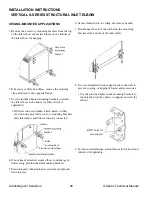
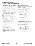
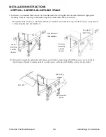
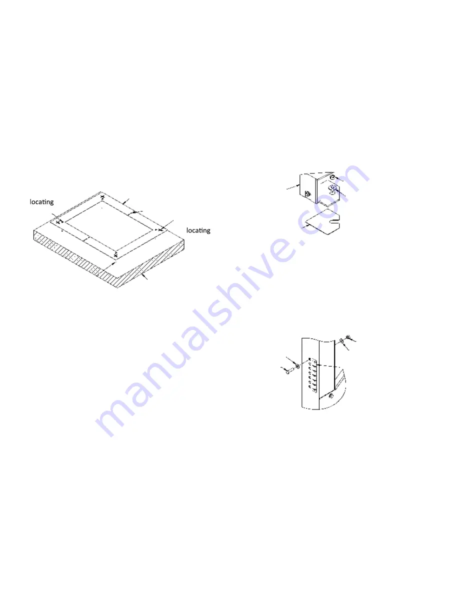
2. Use provided template to mark anchor locations on
existing concrete slab. Consult structural engineer as
to adequacy of existing slab for structural support.
• If no slab available, installation of sonotubes with
housekeeping pad is recommended. Use template to
mark center locations of sono-tubes (indicated with
”+” cutout).
• Install sonotubes as recommended by struc-tural
engineer and use template to mark an-chor locations
(indicated with ”o” hole) on sonotubes.
3. Once concrete/sonotubes are marked, remove and
discard template.
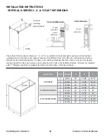
4. Drill holes for anchors.
5. Set stand over anchor locations.
6. Install outdoor rated wedge anchors, minimum
0.5”x6” (not provided), as recommended by
manufacturer into concrete slab/sonotubes where
marked.
7. Make sure stand is both level and square.
• If shimming necessary, insert provided shims where
needed to level the stand.
• Once level and square, secure base to anchors with
washer and lock nut (not provided).
• Shims are NOT intended to be used for ad-justing
the overall stand height. See next step.
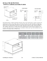
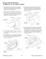
8. Determine if default stand height (48”) is correct for
heater installation.
• If adjustment needed, remove height adjust-ment
bolts (2/leg), and raise stand necessary amount using
the height label as a guide.
• Reattach height adjustment bolts.
Template
Sonotube-
cutouts
Centerline
Anchor-
holes
Drilled holes for
anchors
Concrete slab
Anchor lock nut
Washer
Stand shim
Stand leg
Lock washer
Nut
Washer
Height
adjustment
bolt (2/leg)
Height label
Template
Sonotube-
cutouts
Centerline
Anchor-
holes
Drilled holes for
anchors
Concrete slab
Anchor lock nut
Washer
Stand shim
Stand leg
Lock washer
Nut
Washer
Height
adjustment
bolt (2/leg)
Height label
Template
Sonotube-
cutouts
Centerline
Anchor-
holes
Drilled holes for
anchors
Concrete slab
Anchor lock nut
Washer
Stand shim
Stand leg
Lock washer
Nut
Washer
Height
adjustment
bolt (2/leg)
Height label
Содержание S Series
Страница 93: ...S Series Technical Manual 91 Cambridge Air Solutions REFERENCE ELECTRICAL CONTROL ENCLOSURE ISOMETRIC DRAWING ...
Страница 100: ...Cambridge Air Solutions 98 S Series Technical Manual REFERENCE BUILDING AUTOMATION SYSTEM ...
Страница 112: ...Cambridge Air Solutions 110 S Series Technical Manual MAINTENANCE LOG MODEL NO SERIAL NO Date Activity Technician ...
Страница 113: ...MAINTENANCE LOG MODEL NO SERIAL NO Date Activity Technician ...
Страница 114: ...Cambridge Air Solutions 112 S Series Technical Manual ...
Страница 116: ...760 Long Road Crossing Dr Chesterfield MO 63005 Phone 636 532 2233 800 899 1989 Fax 636 530 6133 www cambridgeair com ...

