Cambridge Air Solutions
104
S-Series Technical Manual
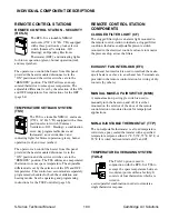
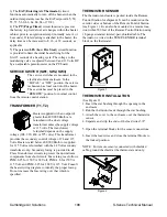
REMOTE TEMPERATURE SENSOR (RTS)
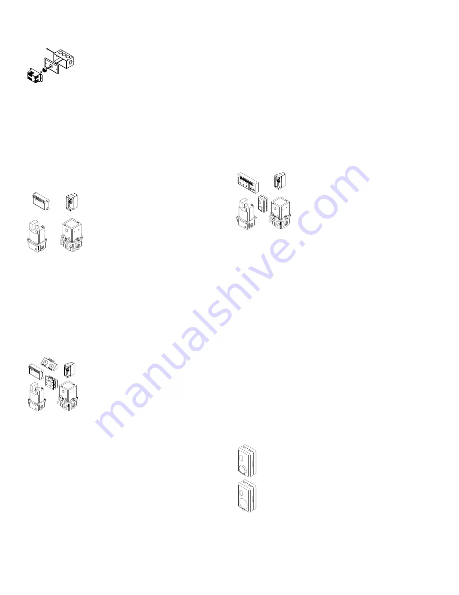
The thermistor is wired to the remote
temperature sensor terminal block. If
remote location of the sensor is desired,
the connecting cable must be wired
between the thermistor and this point.
The thermistor enclosure (SH-1) is
packed in the remote control station for shipment. It
can be mounted on the exterior sides or bottom of the
remote control station or a remote location within 500
feet using 18 gauge stranded, twisted-pair, shielded
cable.
GAS CONTROL SYSTEMS
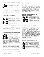
ELECTRONIC DISCHARGE-LOCAL (EDL)
The EDL temperature control system
utilizes Maxitrol’s Series 14
modulation controls. The discharge
temperature sensor, which is
mounted in the discharge, transmits a
resistance signal back to the
amplifier that corresponds to the
discharge temperature. The amplifier
creates a voltage output to drive the modulating valve
to maintain the preselected temperature that is set on
the dial located on the amplifier. This control permits
adjustment of the discharge temperature (110 to 160°F)
from inside the heater control enclosure.
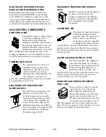
ELECTRONIC DISCHARGE-REMOTE (EDR)
The EDR temperature control
system utilizes Maxitrol’s Series 14
modulation controls. The discharge
temperature sensor, which is
mounted in the discharge, transmits
a resistance signal back to the
amplifier that corresponds to the
discharge temperature. The amplifier creates a voltage
output to drive the modulating valve to maintain the
preselected temperature that is set on the Remote Heat
Adjust (RHA).
Heaters which are specified with a temperature rise of
less than 130˚F are supplied with a single adjusting
knob on the dial face of the RHA. This control permits
manual adjustment of the discharge air temperature
from 55 to 130˚F. The override temperature selector
dial, which is visible from the top of the RHA control,
increases the discharge temperature above the setting
on the dial face by the increment selected (10 to 40˚F)
when a jumper or switch contact is provided across
terminals 20 and 22.
Heaters which are specified with a temperature rise
above 130˚F are supplied with dual adjusting knobs on
the dial face of the RHA. This control permits manual
adjustment of the discharge temperature from 55 to
105˚ or 120 to 160˚F. A jumper or switch contact is
required across terminals 20 and 22 to activate the
higher temperature selection.
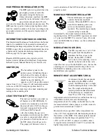
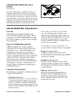
ELECTRONIC DISCHARGE-SPACE
MODULATION (EDSM)
The EDSM temperature control
system utilizes Maxitrol’s Series
44 modulation controls. The Space
Temperature Selector (STS) is set
to the desired space temperature
and it transmits a resistance output
to the amplifier (AMP) to control
the discharge temperature. The
discharge temperature sensor (DTS), which is mounted
in the discharge, transmits a resistance signal back to
the amplifier that corresponds to the discharge
temperature. The amplifier creates a voltage output to
drive the modulating valve (MV) to maintain the
selected space temperature by controlling the heater
output between the MIN and MAX setting on the
amplifier. The MIN dial setting determines the
minimum discharge temperature the heater will deliver
(40 to 80˚F). The MAX dial setting determines the
maximum discharge temperature the heater will deliver
(80 to 160˚F). When the space temperature drifts from
the STS setpoint by more than 3˚F, the modulating
valve is driven to the MIN or MAX discharge
temperature, as applicable.
ELECTRONIC DISCHARGE-SPACE
MODULATION/TAMPER PROOF (EDSM/TP)
The EDSM/TP temperature control system
functions identical to the EDSM control
system. The difference is the STS is replaced
with two devices. The adjustable temperature
selector is typically mounted inside the
remote control station and the non-adjustable
space sensor (RTSS) is mounted in the space.
Содержание S Series
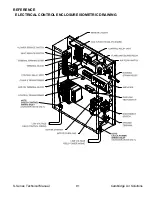
Страница 93: ...S Series Technical Manual 91 Cambridge Air Solutions REFERENCE ELECTRICAL CONTROL ENCLOSURE ISOMETRIC DRAWING ...
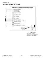
Страница 100: ...Cambridge Air Solutions 98 S Series Technical Manual REFERENCE BUILDING AUTOMATION SYSTEM ...
Страница 112: ...Cambridge Air Solutions 110 S Series Technical Manual MAINTENANCE LOG MODEL NO SERIAL NO Date Activity Technician ...
Страница 113: ...MAINTENANCE LOG MODEL NO SERIAL NO Date Activity Technician ...
Страница 114: ...Cambridge Air Solutions 112 S Series Technical Manual ...
Страница 116: ...760 Long Road Crossing Dr Chesterfield MO 63005 Phone 636 532 2233 800 899 1989 Fax 636 530 6133 www cambridgeair com ...


