S-Series Technical Manual
57
Cambridge Air Solutions
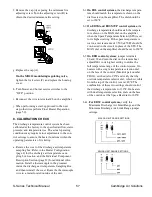
f. Remove the cap (A) exposing the minimum fire
adjusting screw. Turn the adjusting screw (B) to
obtain the desired minimum fire setting.
g. Replace the cap (A).
On the MR212 modulating/regulating valve,
tighten the lock screw (C) and replace the housing
cover.
h. Turn blower and burner service switches to the
“OFF” position.
i. Reconnect the wire to terminal #8 on the amplifier.
j. When performing a start-up proceed to the next
step, otherwise perform Final Heater Preparation
(page 59).
8. CALIBRATION CHECK
The discharge temperature control system has been
calibrated at the factory to the specified airflow, static
pressure, and temperature rise. The actual operating
conditions may require minor adjustments to the con-
trol settings to ensure the heater functions within the
operating parameters of its listing.
a. Remove the cover of the discharge air temperature
sampling box. Refer to the Heater Configuration
(page 4) for the discharge air temperature sam-
pling box location, and the Individual Component
Description Section (page 67) for additional infor-
mation. Install a thermocouple in the grommet
inside the discharge air temperature Sampling Box,
and then reinstall the cover. Route the thermocouple
wire to a meter located outside of the unit.
b.1. On EDL control systems, the discharge tempera-
ture should match the temperature shown on the
dial located on the amplifier. The dial should be
set to 160°F.
b.2. On EDSM and EDSM/TP control systems, the
discharge temperature should match the tempera-
ture shown on the MAX dial on the amplifier
when the Space Temperature Selector (STS) is set
to its highest setting. If the space temperature is
warm, a test resistance of 7,500 ±250 Ω should be
con-nected in the circuit in place of the STS. The
MAX dial on the amplifier should be set to 160°F.
b.3. On EDR control systems, jumper terminals
20 and 22 and turn the dial on the remote heat
adjust RHA to its highest setting to utilize the
full temperature range of the control system. On
heaters with a single temperature selection dial
on the face of the control (Maxitrol part number
TD114), set the dial to 90°F and verify that the
override temperature selector dial, which is visible
from the top of the control, is set at 40°F. The
combination of these two settings should control
the discharge tempera-ture to 130°F. On heaters
with dual temperature selection dials on the face
of the control, set the Space Heat dial to 160°F.
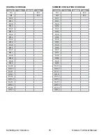
b.4.1. For EDSC control systems, verify the
Maximum Discharge Air Limit Range and the
Minimum Discharge Air Limit Range jumper
settings.
MAX DA LIMIT RANGE SETTINGS
MIN DA LIMIT RANGE SETTINGS
Содержание S Series
Страница 93: ...S Series Technical Manual 91 Cambridge Air Solutions REFERENCE ELECTRICAL CONTROL ENCLOSURE ISOMETRIC DRAWING ...
Страница 100: ...Cambridge Air Solutions 98 S Series Technical Manual REFERENCE BUILDING AUTOMATION SYSTEM ...
Страница 112: ...Cambridge Air Solutions 110 S Series Technical Manual MAINTENANCE LOG MODEL NO SERIAL NO Date Activity Technician ...
Страница 113: ...MAINTENANCE LOG MODEL NO SERIAL NO Date Activity Technician ...
Страница 114: ...Cambridge Air Solutions 112 S Series Technical Manual ...
Страница 116: ...760 Long Road Crossing Dr Chesterfield MO 63005 Phone 636 532 2233 800 899 1989 Fax 636 530 6133 www cambridgeair com ...

