S-Series Technical Manual
89
Cambridge Air Solutions
1. Before reinstalling the damper motor into the heater
assembly, remove the black plastic weather cover
from the damper motor by removing the screw that
secures the cover to the damper assembly using
either a flat tip screw driver or a ¼” nut driver.
It may be necessary to twist the cover slightly to
disengage it from its mounting to the end of the
motor after the screw is removed.
2. Verify the damper motor is in the CLOSED
position (Drive tube is retracted with a minimum of
1/4” gap between the drive tube and the body of the
damper assembly).
3. Verify the inner cam has fully engaged the lower
limit switch plunger and the lower limit switch
(next to the body of the damper motor) shows
continuity between the common (C) terminal and
the normally open (NO) terminal.
m
CAUTION:
If the lower limit switch does not indicate
continuity, the damper motor must be driven to
the fully CLOSED position BEFORE connecting
the damper linkage tube to drive tube of damper
motor assembly.
IMPORTANT
If the drive tube bottoms out against the damper
motor housing, damage to the PC board or tripping
of the onboard fuse may result. If the fuse trips, place
the blower service switch in the OFF position for 15
seconds to allow fuse to reset. Proceed with steps 4
through 10 PRIOR to connecting the damper motor to
the linkage tube.
4. Verify the cam location on the upper cam is set just
short of the four o’clock position with respect to the
switch plunger being the twelve o’clock reference
position. If it is beyond the four o’clock position,
use a deep well 1/2” hex socket or nut driver and
manually rotate the cam counterclockwise a few
clicks, as required, to obtain the correct starting
position. (Refer to Figure 1.)
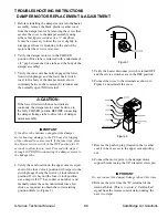
Figure 1
5. Verify the heater disconnect switch is turned OFF
and the service switches are in the OFF position.
6. Connect the wires to the terminals as shown in
Figure 2 and reinstall the cover.
Figure 2
7. Remove the push-in plug (located in the weather
cover) to have access to the upper cam adjusting
nut.
8. Connect the motor pivot to the damper motor
support bracket using the 3/8” diameter clevis pin.
IMPORTANT
Do not connect the damper linkage tube at this time.
9. Remove the wire from the ”G” terminal of the
terminal block. (This is to avoid a ”Call-for-Fan”
signal from the remote control station during the
next two steps).
TROUBLESHOOTING INSTRUCTIONS
DAMPER MOTOR REPLACEMENT & ADJUSTMENT
Содержание S Series
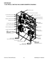
Страница 93: ...S Series Technical Manual 91 Cambridge Air Solutions REFERENCE ELECTRICAL CONTROL ENCLOSURE ISOMETRIC DRAWING ...
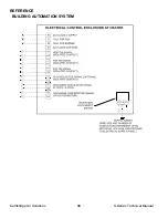
Страница 100: ...Cambridge Air Solutions 98 S Series Technical Manual REFERENCE BUILDING AUTOMATION SYSTEM ...
Страница 112: ...Cambridge Air Solutions 110 S Series Technical Manual MAINTENANCE LOG MODEL NO SERIAL NO Date Activity Technician ...
Страница 113: ...MAINTENANCE LOG MODEL NO SERIAL NO Date Activity Technician ...
Страница 114: ...Cambridge Air Solutions 112 S Series Technical Manual ...
Страница 116: ...760 Long Road Crossing Dr Chesterfield MO 63005 Phone 636 532 2233 800 899 1989 Fax 636 530 6133 www cambridgeair com ...

