Installing signal/control and power cables
General notes
Interference emissions!
Risk of injury due to malfunction and uncon‐
trolled movements!
CAUTION
●
Eliminate sources of interference in the area of the signal and control
cables!
●
Ensure an installation in line with EMC requirements.
The achievable operating time of the cables is to a great extent determined
by the type of installation and environmental influences at the place of use.
Due to the large variety of application conditions, the listed basic recommen‐
dations for the handling of cables can, however, only serve as an aid to en‐
sure a long and fault-free operation of the cables.
●
Lay cables and lines so that they cannot be damaged and no one can
trip over them.
●
Never subject cables to pulling stress or torsion. Mechanically fix the ca‐
ble ends in place after no more than approx. 30 cm (e.g. cable clip, ca‐
ble binder, etc.)
●
Do not kink cables. Do not fall below the bending radii. The value of the
bending radius should be at least 5-6 times the diameter of the cable.
●
Do not subject cables to large temperature differences and extreme
weather influences. Always store cables in a dry place.
●
Always unroll cables completely.
●
Never use damaged cables (e.g. by pressure, clamping or crushing). In
case of damage, shut the system down and replace the cables.
●
Check the connection cables at regular intervals for damage and ex‐
change them, if necessary.
●
Check the connections for the protective earthing conductor at regular
intervals for proper condition and tight seat.
●
Do not use any silicone-containing sealants, adhesives or insulating
agents.
●
Ensure a maintenance-friendly installation, i.e. simple access to the con‐
nection lines. Ensure free access to the connection side.
●
Before the installation note down the information on the nameplates. If
after the installation nameplates are not visible or readable any more,
this data will be available to you at any time.
Cable routing
●
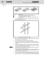
Install signal and control lines with a minimum clearance of 100 mm,
preferably 200 mm, or using a grounded partition plate to separate them
from the power cables. The installation in separate cable ducts is the
optimum. Whenever possible, introduce signal lines only at one place in‐
to the control cabinet in which the drive controller is installed.
●
Renew cable markings and warning notes on cable connections which
have become illegible or were lost.
Operating Instructions
Bosch Rexroth AG
37/91
Self-contained servo-hydraulic linear axis Type SHA...
Installation
Содержание Rexroth SHA Series
Страница 1: ...Self contained servo hydraulic linear axis Type SHA Operating Instructions RE 62266 B_12 18 Edition 1 ...
Страница 6: ...Bosch Rexroth AG Operating Instructions IV 91 Self contained servo hydraulic linear axis Type SHA ...
Страница 20: ...Bosch Rexroth AG Operating Instructions 18 91 Self contained servo hydraulic linear axis Type SHA ...
Страница 48: ...Bosch Rexroth AG Operating Instructions 46 91 Self contained servo hydraulic linear axis Type SHA ...
Страница 60: ...Bosch Rexroth AG Operating Instructions 58 91 Self contained servo hydraulic linear axis Type SHA ...
Страница 68: ...Bosch Rexroth AG Operating Instructions 66 91 Self contained servo hydraulic linear axis Type SHA ...
Страница 74: ...Bosch Rexroth AG Operating Instructions 72 91 Self contained servo hydraulic linear axis Type SHA ...
Страница 76: ...Bosch Rexroth AG Operating Instructions 74 91 Self contained servo hydraulic linear axis Type SHA ...
Страница 78: ...Bosch Rexroth AG Operating Instructions 76 91 Self contained servo hydraulic linear axis Type SHA ...
Страница 86: ...Bosch Rexroth AG Operating Instructions 84 91 Self contained servo hydraulic linear axis Type SHA ...
Страница 88: ...Bosch Rexroth AG Operating Instructions 86 91 Self contained servo hydraulic linear axis Type SHA ...
Страница 90: ...Bosch Rexroth AG Operating Instructions 88 91 Self contained servo hydraulic linear axis Type SHA ...
Страница 93: ...Notes Operating Instructions Bosch Rexroth AG 91 91 Self contained servo hydraulic linear axis Type SHA ...


