2.
Manually tighten the cap nut of the power connector. By feeding in the
cable, the power connector can be pushed further forward until it rea‐
ches its end position.
3.
Tighten the cap nut until the limit stop.
Only completely tightened cap nuts ensure the specified IP pro‐
tection class and activate vibration protection.
The servo motor is directly connected to the drive controller using the motor
power and motor encoder cables which are included in the scope of delivery.
The motor power cable is to be connected to the power section via interfaces
X5 and X6, the motor encoder cable is to be connected to the control section
using interface X8.
For a detailed description of the electrical interfaces and the wir‐
ing diagrams, please refer to the related documentation (electrical
wiring diagram) from Bosch Rexroth.
Connecting the internal position
measuring system -B1
In the standard version, the self-contained servo-hydraulic linear axis is
equipped with an integrated position measuring system, preferably of type
BTL7 made by Balluff, in interface variant “S115“ (M12, 8-pin). This has to be
connected to interface X4 on the control section via a cable connection. The
required connection cable is not included in the scope of delivery.
Connection cables of various variants with open cable ends can be pur‐
chased from Balluff. At the open end, these cables have to be assembled
with a 15-pin female D-Sub plug-in connector.
Connection cable fur BTL7 in the interface variant “S115“ (M12, 8-pin) from
Balluff:
Ordering code
Type designation Variant
BCC00YF
BKS-S115-PU-05 5 m, shielded, straight coupling
BCC00YH
BKS-S115-PU-10 10 m, shielded, straight coupling
BCC00YJ
BKS-S115-PU-15 15 m, shielded, straight coupling
BCC00YW
BKS-S116-PU-05 5 m, shielded, angled coupling
BCC00YY
BKS-S116-PU-10 10 m, shielded, angled coupling
BCC00YZ
BKS-S116-PU-15 15 m, shielded, angled coupling
Tab. 7-1:
Connection cable for BTL7 in the interface variant “S115“ (M12, 8-
pin) from Balluff
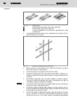
Connection diagram:
Fig. 7-3:
Connection for BTL7 in the interface variant “S115“
Bosch Rexroth AG
Operating Instructions
40/91
Self-contained servo-hydraulic linear axis Type SHA...
Installation
Содержание Rexroth SHA Series
Страница 1: ...Self contained servo hydraulic linear axis Type SHA Operating Instructions RE 62266 B_12 18 Edition 1 ...
Страница 6: ...Bosch Rexroth AG Operating Instructions IV 91 Self contained servo hydraulic linear axis Type SHA ...
Страница 20: ...Bosch Rexroth AG Operating Instructions 18 91 Self contained servo hydraulic linear axis Type SHA ...
Страница 48: ...Bosch Rexroth AG Operating Instructions 46 91 Self contained servo hydraulic linear axis Type SHA ...
Страница 60: ...Bosch Rexroth AG Operating Instructions 58 91 Self contained servo hydraulic linear axis Type SHA ...
Страница 68: ...Bosch Rexroth AG Operating Instructions 66 91 Self contained servo hydraulic linear axis Type SHA ...
Страница 74: ...Bosch Rexroth AG Operating Instructions 72 91 Self contained servo hydraulic linear axis Type SHA ...
Страница 76: ...Bosch Rexroth AG Operating Instructions 74 91 Self contained servo hydraulic linear axis Type SHA ...
Страница 78: ...Bosch Rexroth AG Operating Instructions 76 91 Self contained servo hydraulic linear axis Type SHA ...
Страница 86: ...Bosch Rexroth AG Operating Instructions 84 91 Self contained servo hydraulic linear axis Type SHA ...
Страница 88: ...Bosch Rexroth AG Operating Instructions 86 91 Self contained servo hydraulic linear axis Type SHA ...
Страница 90: ...Bosch Rexroth AG Operating Instructions 88 91 Self contained servo hydraulic linear axis Type SHA ...
Страница 93: ...Notes Operating Instructions Bosch Rexroth AG 91 91 Self contained servo hydraulic linear axis Type SHA ...


