background image

RediStart MX

 2

 - SEP Synchronous Controller User Manual                                     

98

Содержание RediStart MX2 SEP

Страница 1: ...tate Starter SEP Synchronous Control RediStart TM User Manual MX SEP Models Benshaw retains the right to change specifications and illustrations in text without prior notification The contents of this document may not be copied without the explicit permission of Benshaw ADVANCED CONTROLS DRIVES ...

Страница 2: ......

Страница 3: ...and operation Keep this manual on hand for reference Do not attempt to install operate maintain or inspect the controller until you have thoroughly read this manual and related documents carefully and can use the equipment correctly Do not use the controller until you have a full knowledge of the equipment safety procedures and instructions This instruction manual classifies safety instruction lev...

Страница 4: ...Apply only the voltage specified in this manual to the terminals to prevent damage Transportation and Installation To prevent injury use proper lifting gear when carrying products Ensure that the installation position and materials can withstand the weight of the controller Refer to the installation information in this manual for correct installation If parts are missing or the synchronous control...

Страница 5: ...iderations 21 3 4 Wiring Considerations 22 3 4 1 Wiring Practices 22 3 4 2 Considerations for Control and Power Wiring 22 3 4 3 Considerations for Signal Wiring 22 3 4 4 Meggering a Motor 22 3 4 5 High Pot Testing 22 3 5 Power and Control Drawings 23 3 5 1 MX2 ATL Synchronous Brushtype Field Control Solid State 23 3 5 2 MX2 ATL Synchronous Brushtype with contactors 24 3 5 3 MX2 ATL Synchronous Bru...

Страница 6: ...Keypad and Display 43 4 10 Description of the LEDs on the Keypad 43 4 11 Description of the Keys on the Remote LCD Keypad 44 4 12 Alphanumeric Display 45 4 12 1 Power Up Screen 45 4 12 2 Operate Screen 45 4 12 3 Parameter Group Screens 46 4 12 4 Meter Pages 47 4 12 5 Fault Log Screen 48 4 12 6 Fault Screen 48 4 12 7 Lockout Screens 49 4 12 8 Alarm Screen 49 4 13 Procedure for Setting Data 50 5 PAR...

Страница 7: ... Information 99 8 2 2 Preventive Maintenance 99 8 3 General Troubleshooting Charts 100 8 3 1 Motor does not start no output to motor 100 8 3 2 During starting motor rotates but does not reach full speed 100 8 3 3 Motor stops unexpectedly while running 100 8 3 4 Metering incorrect Hall Effect 101 8 3 5 Other Situations 101 8 4 Fault Code Table 102 8 5 SCR Testing 106 8 5 1 Resistance 106 8 5 2 Volt...

Страница 8: ...RediStart MX 2 SEP Synchronous Controller User Manual 8 ...

Страница 9: ...ECTRIC SHOCK EXPLOSION OR ARC FLASH Only qualified personnel familiar with low or medium voltage equipment are to perform work described in this set of instructions Apply appropriate personal protective equipment PPE and follow safe electrical work practices See NFPA 70E Turn off all power before working on or inside equipment Use a properly rated voltage sensing device to confirm that the power i...

Страница 10: ... information about contacting technical support personnel refer to Page 11 Documentation Benshaw provides all customers with Operations manual Wiring diagrams All drawings are produced in AutoCAD format The drawings are available via e mail by contacting Benshaw Replacement Parts Spare and replacement parts can be purchased from Benshaw Technical Support Software Number This manual pertains to sof...

Страница 11: ...nshaw Customer Service department at one of the above telephone numbers A service technician is available Monday through Friday from 8 00 a m to 5 00 p m EST NOTE An on call technician is available after normal business hours and on weekends by calling Benshaw and following the recorded instructions To help assure prompt and accurate service please have the following information available when con...

Страница 12: ...reting Model Numbers Figure 1 RediStart MX2 SEP Series Model Numbers MX2SEP 125VDC 50A 3 S C C Open Chassis 1 Single Phase Bridge 3 Three Phase Bridge M Mechanical contactors S Solid State Current Rating of Bridge Voltage Rating of Field 125 or 250 VDC MX2 Control ...

Страница 13: ...med for synchronous motor fields The RediStart MX2 SEP can also protect the motor and its load from damage that could be caused by incorrect phase order wiring The controller continually monitors the amount of current being delivered to the motor This protects the motor from overheating or drawing excess current Features Enhanced engineering features of the controller include Multiple frame sizes ...

Страница 14: ...RediStart MX 2 SEP Synchronous Controller User Manual 14 ...

Страница 15: ...R1 TB2 NO1 Normally Open Contact RC1 Common NC1 Normally Closed Contact Relay Output SPDT form C NO Contact resistive NC Contact resistive 5A at 250VAC 3A at 250VAC 5A at 125VAC 3A at 125VAC 5A at 30VDC 3A at 30VDC 1250VA 750VA Relay 2 R2 TB2 NO2 Normally Open Contact RC2 Common Contact NC2 Normally Closed Contact Relay Output SPDT form C NO Contact resistive NC Contact resistive 5A at 250VAC 3A a...

Страница 16: ...A maximum Current 0 20mA 500Ω load maximum Display RJ45 Door Mounted Display Connector SCR J6 to J11 1 Gate 2 Cathode SCR Gate Connections Table 1 Terminals Continued Function Terminal Block Terminal Number Description Table 2 Measurements and Accuracies Internal Measurements Hall Effect Input Conversion True RMS Sampling 1 562kHz Range 1 1000A Line Voltage Inputs Conversion True RMS Sampling 1 56...

Страница 17: ...nd time 0 1 to 90 0 sec in 0 1 sec intervals ANSI 47 Phase rotation selectable ABC CBA Insensitive or Single Phase ANSI 48 Adjustable up to speed stall timer 1 to 900 sec in 1 sec intervals ANSI 51 Overcurrent detection Off or 50 to 800 and time 0 1 to 90 0 sec in 0 1 sec intervals ANSI 56 Field Application ANSI 74 Alarm relay output available ANSI 81 Over Under Frequency ANSI 95 Reluctance torque...

Страница 18: ...UL Recognized 2 6 Certificate of Compliance CE Mark see Appendix D on Page 117 Table 3 Environmental Ratings Operating Temperatures 10 C to 40 C 14 F to 104 F enclosed 10 C to 50 C 14 F to 122 F open Storage Temperatures 20 C to 70 C 4 F to 155 F Humidity 0 to 95 non condensing Altitude 1000m 3300ft without derating Maximum Vibration 5 9m s2 19 2ft s2 0 6G Cooling Natural convection Fans optional ...

Страница 19: ...tage for the application has been purchased 3 1 2 Installation Precautions Installation of some models may require halting production during installation If applicable ensure that the controller is installed when production can be halted long enough to accommodate the installation Before installing the controller ensure The wiring diagram supplied separately with the controller is correct for the ...

Страница 20: ...ed from debris metal shavings and any other foreign objects NOTE The opening of the branch circuit protective device may be an indication that a fault current has been interrupted To reduce the risk of electrical shock current carrying parts and other components of the controller should be inspected and replaced if damaged 3 2 Installation Considerations 3 2 1 Site Preparation General Information ...

Страница 21: ...otection on the starter can be set to provide overcurrent protection of the stator windings in cases such as the rotor puling out of synchronization Additionally a low Power Factor trip can be used to detect when the rotor is no longer synchronized 3 3 Mounting Considerations Provisions should be made to ensure that the temperature inside the enclosure never rises above 122oF 50oC If the temperatu...

Страница 22: ... for 460VAC and 600VAC systems Grounding must be in accordance with NEC CEC or local codes If multiple controllers are installed near each other each must be connected to ground Take care to not form a ground loop Grounds should be connected in a STAR configuration Wire must be made of copper and rated 60 75 C for units 124 Amps and below Larger amp units may use copper or aluminum wire Refer to N...

Страница 23: ...3 Installation 23 3 5 Power and Control Drawings 3 5 1 MX2 ATL Synchronous Brushtype Field Control Solid State Figure 2 Sample Power Schematic for RB2 Low HP ...

Страница 24: ...RediStart MX 2 SEP Synchronous Controller User Manual 24 3 5 2 MX2 ATL Synchronous Brushtype with contactors Figure 3 Sample MX2 Power Schematic ATL Synchronous Brushtype with contactors ...

Страница 25: ...3 Installation 25 3 5 3 MX2 ATL Synchronous Brushless Figure 4 Sample MX2 Power Schematic ATL Synchronous Brushless ...

Страница 26: ...RediStart MX 2 SEP Synchronous Controller User Manual 26 3 5 4 Synch Controller with Power Factor Control Figure 4 Sample Power Schematic Synch Controller with Power Factor Control ...

Страница 27: ... over the NEC Refer to your local requirements 3 6 3 Power Wire Connections Attach the motor cables Use the F and F terminals Use lugs crimps or terminals Lugs and Crimps are to be provided by the user Attach the power source cables Use the L1 L2 and L3 terminals Use lugs crimps or terminals Lugs and Crimps are to be provided by the user 3 6 4 Compression Lugs The following is a list of the recomm...

Страница 28: ...ess and slot length inch 6 4mm or less Slot width over 0 047 inch 1 2mm or slot length over inch 6 4mm or less Split bolt connectors Other connectors 18 10 0 82 5 3 20 2 3 35 4 0 80 9 0 75 8 5 8 8 4 25 2 8 40 4 5 80 9 0 75 8 5 6 4 13 3 21 2 35 4 0 45 5 1 165 18 6 110 12 4 3 26 7 35 4 0 50 5 6 275 31 1 150 16 9 2 33 6 40 4 5 50 5 6 275 31 1 150 16 9 1 42 4 50 5 6 275 31 1 150 16 9 1 0 2 0 53 5 64 4...

Страница 29: ...1 3 P42 44 Modbus Communications Port FUN 10 13 P66 69 Keypad Port I O 14 P55 Analog Output I O 09 11 P50 52 Analog Voltage Current Selector Switch SW1 Part Serial Reset Parameter Down Up Enter Software Part 120 VAC Stack In Benshaw Only Stack Control SCR 1 SCR 4 SCR 2 SCR 5 SCR 3 SCR 6 4x7 LED Display TB5 RJ45 Hall Effect Transformer Jumper RX LED TX LED CPU LED ...

Страница 30: ... Digital Inputs I O 1 3 P42 44 Modbus Communications Port FUN 10 13 P66 69 Keypad Port I O 14 P55 Analog Output I O 09 11 P50 52 Analog Voltage Current Selector Switch SW1 Part Serial Reset Parameter Down Up Enter Software Part 120 VAC Stack In Benshaw Only Stack Control SCR 1 SCR 4 SCR 2 SCR 5 SCR 3 SCR 6 TB5 RJ45 Hall Effect Transformer Jumper Fiber Optic Connections 4x7 LED Display RX LED TX LE...

Страница 31: ...ay 1 normally open 2 RC1 Relay 1 common 3 NC1 Relay 1 normally closed 4 NO2 Relay 2 normally open 5 RC2 Relay 2 common 6 NC2 Relay 2 normally closed 7 NO3 Relay 3 normally open 8 RC3 Relay 3 common 9 NC3 Relay 3 normally closed Figure 8 Relay Wiring Examples See Also Relay Output Configuration I O 05 07 P44 46 on Page 76 120VAC LIVE 120VAC NEUTRAL TRIP TRIP PILOT LIGHT RELAY 1 SET TO FLFS FAULT FA...

Страница 32: ...C neutral Figure 9 Digital Input Wiring Examples See Also Digital Input Configuration I O 01 03 P40 42 on Page 75 120VAC LIVE 120VAC NEUTRAL 120VAC LIVE 120VAC NEUTRAL START DI1 DI2 DI3 120VAC LIVE 120VAC NEUTRAL 120VAC NEUTRAL 120VAC LIVE 120VAC NEUTRAL FAULT RESET DIGITAL INPUT WIRING 2 WIRE CONTACT CONTROL FAULT RESET BUTTON 3 WIRE START STOP BUTTONS EXTERNAL TRIP INPUT DI2 SET TO Fr FAULT RESE...

Страница 33: ...The output will be damaged if control power 115VAC or line power is applied to the analog output The terminals are as follows Figure 10 Analog Output Wiring Example 5 analog output 6 common 7 shield See Also Analog Output Configurations I O 9 11 P54 56 on Pages 77 and 78 3 8 5 SW1 DIP Switch The SW1 DIP switch on the card allows selecting the analog input and output values of 0 10V or 0 20mA The p...

Страница 34: ...lay as P N KPMX3LLCD 3 9 1 Remote Display The LCD keypad is mounted remotely from the MX2 Control via a straight through display cable which connects between the MX2 and remote display s RJ45 terminals 3 9 2 Display Cutout Figure 12 Small Display Keypad Mounting Dimensions Part KPMX3SLCD Figure 13 Large Display Keypad Mounting Dimensions Part KPMX3LLCD 50 50 1 99 50 50 1 99 31 50 1 24 31 50 1 24 1...

Страница 35: ...old the display securely in place Torque requirements are 0 7 NM or 6 195 in lbs Plug the cable into the display connector on the MX2 card See Figures 5 and 6 on Pages 29 and 30 for the connector location Route the cable through the enclosure to the display Observe the wiring considerations as listed in Section 3 4 on Page 22 Plug the other end of the cable into the LCD display Figure 14 Mounting ...

Страница 36: ...RediStart MX 2 SEP Synchronous Controller User Manual 36 ...

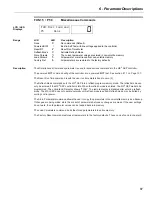
Страница 37: ...ming The 4 digit 7 segment display shows controller meter outputs and programming data Special symbols provide further information about the controller operation see the following section Figure 15 Standard Keypad and Display 4 3 Viewing Parameter Values for the Standard Keypad Parameter view mode can be entered by 1 At the default meter display press the PARAM key to enter parameter mode P1 is di...

Страница 38: ...parameter can be viewed by pressing the ENTER key 4 When viewing the parameter value the parameter can be changed by using the UP and DOWN keys 5 To store the new value press the ENTER key When the ENTER key is pressed the value is saved and the display goes back to parameter P_ To exit parameter change mode without saving the new parameter value either 1 Press the PARAM key to return to the param...

Страница 39: ... Inching field control mode active dynb Dynamic braking active L CP Low Control Power A start is not allowed because the control power is low L Ot Power Stack Over Temperature Lockout LOC Lockout State AbC Phase order meter showing ABC phasing CbA Phase order meter showing CBA phasing SPH Phase order meter showing single phase P xx XX parameter code A xx XX alarm code If the condition persists a f...

Страница 40: ...Slip Percent Run Days Ave Volts Phase Order Run Hours L1 L2 Volts Input Line Freq Starts L2 L3 Volts Input Analog Input L3 L1 Volts Input Analog Out LCD Display Stopped Controller stopped Fault Controller tripped on a Fault Lockout Controller is locked out due to a unusual condition being present Wait Controller is monitoring start and waiting for command and or timer to expire before applying fie...

Страница 41: ... second intervals 4 5 6 Faulted Condition When a fault condition exists the display shows the fault code The exceptions to this are as follows When the fault is Instantaneous Over Current ioc is displayed 4 5 7 Quick Meters Although any meter may be viewed by changing the Meter parameter P17 FUN 01 02 there are 3 Quick Meters that are always available with a single key press When the controller is...

Страница 42: ...gs press and hold the PARAM and ENTER pushbutton switch on power up The display blinks dFLt Parameters unique to the controller applications need to be set again to appropriate values before motor operation P23 FUN06 Rated RMS Voltage set to specified equipment rating I O 01 P40 Digital Input 1 P41 I O 02 Digital Input 2 P42 I O 03 Digital Input 3 P44 I O 05 Relay 1 P45 I O 06 Relay 2 P46 I O 07 R...

Страница 43: ...al information for controller operation NOTE The Start push button does not operate with a synchronous controller Figure 16 Remote LCD Keypad 4 10 Description of the LEDs on the Keypad The keypad provides three LED indicators in addition to the 2x16 character display The LEDs provide controller status information NOTE By default the STOP key is always active regardless of selected control source L...

Страница 44: ...en the first parameter is displayed it scrolls to the end of the list When a list of faults is displayed it moves from one fault to the previous fault When the controller is in the Operate Mode pressing DOWN allows you to change which group of meter val ues is monitored When editing a numeric parameter the LEFT arrow key moves the cursor one digit to the left If cursor is already at the most signi...

Страница 45: ... is in and display the values of Meter 1 and Meter 2 which are selectable The Operate Screen is divided into five sections Sections A and B display status information Sections C and D display the meters selected by the Meter 1 and 2 parameters see FUN 01 02 Section S displays the source for the start command Figure 17 Operate Screen Table 12 Operate Screen Section A Display Description noL L1 L2 L...

Страница 46: ...nd Units Refer to Section 5 for a listing of the parameters and ranges Syncing Controller is attempting to apply field and synchronize motor Synced Motor running synchronized Sync FF Motor running synchronized with field forcing active Pullout Motor pullout pole slip detected B Ctl Brushless motor control active Cntr Current Control mode active Inching Inching field control mode active Braking Dyn...

Страница 47: ...ccessed to view all of the meter information These meter pages are scrolled through by pressing the UP or DOWN arrows from the operate screen Current 0 0A Slip Perce 0 0A Voltage V2 0V V1 0 V3 0V Frequency 0 0H Phase noL Run Days xxxx Run Hours xx xx Analog In 0 1 Analog Out 0 0 Starts xxxx NOTE Run Hours 00 00 23 59 Run Days 0 2730 days or 7 5 years Starts 0 65535 ...

Страница 48: ...through the steps shown below which detail the controller conditions when the fault occurred 4 12 6 Fault Screen When a Fault occurs the Main Screen is replaced with a Fault Screen The screen shows the fault number and the name of the fault The Main Screen is not shown until the fault is reset When a fault occurs the STOP LED flashes Fault Fault Name NOTE For a list of the Faults refer to Appendix...

Страница 49: ...played if a stack over temperature is detected Stack Overload Lockout The control power lockout will be displayed if control power is not within specifications Control Power Lockout 4 12 8 Alarm Screen When an alarm is present the word Alarm is displayed on the operate screen and the Alarm LED indicators on the Control Board are illuminated Pressing the ENTER key displays more information about th...

Страница 50: ...ccess Motor FLA QST 01 QST Cur Setpoint 01 10 Amp Press ENTER key once the cursor starts to flash in the ones place QST Cur Setpoint 01 10 Amp Press LEFT key once the cursor flashes in the tens place QST Cur Setpoint 01 10 Amp Press UP arrow to increase the value for a value of 30 press twice QST Cur Setpoint 01 30 Amp Press ENTER to store the value QST Cur Setpoint 01 30 Amp Press UP arrow to cha...

Страница 51: ...Operate Screen QST Group CFN Group PFN Group I O Group FUN Group Fault History 10 00 CFN Slip Percent 01 5 0 02 CFN F Force Lvl 03 120 QST Jump Code QST F Apply Dly 02 Off QST Inc Seq Time 03 30 sec Current x xA V1 0 V3 0V Frequency 0 0H Phase noL QST Remote Src 05 Terminal In any of the parameter groups the user can jump to a specific parameter code by following these steps Select a parameter gro...

Страница 52: ...RediStart MX 2 SEP Synchronous Controller User Manual 52 ...

Страница 53: ...s PFN Protection Functions I O Input Output Functions FUN Function and FL1 Faults When the standard on board LED display is used the parameters are in a single group and numbered P1 P2 P3 etc LCD parameters are divided into groups of related functionality and within the groups the parameters are identified by a short descriptive name They are numbered by the group name followed by an index within ...

Страница 54: ...L Field Contactor s Feedback Time 79 P14 CFN 09 B Inch Field Level 66 P58 I O 14 B BL CF Keypad Stop Enabled 80 P15 CFN 10 B Inch Field Application Time 66 P57 I O 15 B BL CF Auto Start 80 P16 CFN 11 B Inch UTS Relay Delay Time 66 P17 FUN 01 B BL CF LCD Meter 1 81 P18 PFN 01 B Open Field Trip Time 67 N A FUN 02 B BL CF LCD Meter 2 81 P19 PFN 02 B BL CF Over Current Level 68 P35 FUN 03 B BL CF HE S...

Страница 55: ...cation Time Field Application Time OFF 0 1 20 0 sec OFF Y 60 QST 03 P6 Incomplete Sequence Time Incomplete Sequence Time 1 200 sec 30 Y 61 QST 04 P37 Local Control Source Local Control Source TEr Terminal SEr Serial Terminal Y 61 QST 05 P38 Remote Control Source Remote Control Source TEr Terminal SEr Serial Terminal N 61 Table 17 Control Function Group Group LED Display Parameter Setting Range Uni...

Страница 56: ... Undr Vlt Lvl Under Voltage Level OFF 1 40 OFF Y 70 PFN 08 P26 Vlt Trip Tim Over Under Voltage Trip Time 0 1 90 0 sec 0 1 Y 70 PFN 09 P27 Ph Loss Time Phase Loss Trip Time 0 1 5 0 sec 0 2 Y 71 PFN 10 P28 Over Frq Lvl High Line Frequency Trip 24 72 Hz 72 Y 71 PFN 11 P29 Undr Frq Lvl Low Line Frequency Trip 23 71 Hz 23 Y 71 PFN 12 P30 Frq Trip Tim Frequency Trip Time 0 1 90 0 sec 0 1 Y 72 PFN 13 P31...

Страница 57: ...m rdYr Ready LOC Locked Out OC Overcurrent UC Undercurrent ShFS Shunt Trip FS SHnF Shunt Trip NFS FS1 Field supply contactor FS2 Field discharge resistor contactor FcA Field Contactor Aux dYnb Dyn Braking FAn Cool Fan Ctl SIFS N 76 I O 06 P45 R2 Config R2 Configuration Relay 2 FS1 I O 07 P46 R3 Config R3 Configuration Relay 3 Running I O 08 P47 FCA Delay FCA Time Delay OFF 0 1 90 0 sec OFF Y 77 I ...

Страница 58: ...rder ABC CBA INS SPH INS N 83 FUN 06 P23 Rated Volts Rated Input Voltage 100 110 120 200 208 220 230 240 320 350 380 400 415 440 460 480 500 525 575 600 660 690 800 1000 1140 Vrms 120 N 83 FUN 07 P60 Rated PF Rated Power Factor 0 10 0 10 1 0 Y 84 FUN 08 P61 Min PF Curr Minimum PF Control Current 40 100 60 Y 84 FUN 09 P39 Control Type Controller Type Fld Field Control BruS Brushless Control Cur Cur...

Страница 59: ...ally appears on the remote mounted LCD keypad and the built in display respectively On the LCD the parameter group represented above by MMM and the possibly abbreviated parameter name are shown on the first line The parameter group number represented above by MI for menu index and the parameter s value and units are shown on the second line Some parameters appear in two different menus of the LCD ...

Страница 60: ...is when FUN 09 P39 is set to Brush Type The field apply delay timer will delay the application of the field after the motor has reached the slip speed CFN 01 P2 The following is when FUN 09 P39 is set to Brushless Control The field apply delay timer will delay the application of the field when a start command is received In most cases this should be set to a long enough time to allow the motor to ...

Страница 61: ...Two parameters Local Source QST 04 P37 and Remote Source QST 05 P38 select the source of the start and stop control If a digital input is programmed as Local Remote then that input selects the control source When the input is low the local source is used When the input is high the remote source is used If no digital input is programmed as Local Remote then the local remote bit in the controller co...

Страница 62: ...rce is used When the input is high the remote source is used If no digital input is programmed as Local Remote then the local remote bit in the controller control Modbus register selects the control source The default value of the bit is Local 0 Figure 16 Local Remote Source See Also Local Source QST 04 P36 parameter on Page 61 Digital Input Configuration I O 01 03 P40 42 parameters on Page 75 Key...

Страница 63: ...ed NOTE Brush type motor only FUN 09 P39 set to Field Type CFN 02 P3 Field Apply Dly LCD LED Displays CFN F Apply Dly 02 Off Range Off 0 1 20 0 Default Off Description The following is when FUN 09 P39 is set to Brush Type The field apply delay timer will delay the application of the field after the motor has reached the slip speed CFN 01 P2 The following is when FUN 09 P39 is set to Brushless Cont...

Страница 64: ... system will apply the field forcing current before dropping to the programmed current NOTE Not used in Current Control mode FUN 09 P39 CFN 05 P10 Stop Mode LCD LED Displays CFN Stop Mode 05 Coast Range Coast Dyn Brake Default Coast Description One of two Stop Modes can be chosen Coast When Coast mode is selected the controller will immediately remove the DC field when a stop command is received T...

Страница 65: ... P12 Dynamic Brake Time LCD LED Displays CFN Brake Time 07 5 sec Range 1 180 seconds Default 5 Description The dynamic brake time sets the amount of time that the brake relay is energized The brake relay is used to connect the dynamic braking resistor NOTE See Dynamic Braking in Theory of Operation on Page 97 CFN 08 P13 Dynamic Brake Delay LCD LED Displays CFN Brake Delay 08 0 5 sec Range 0 1 5 0 ...

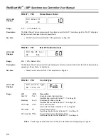
Страница 66: ... Inch Field Application Time CFN 10 P15 on Page 66 Inch UTS Delay CFN 11 P16 on Page 66 Digital Inputs I O 01 03 P40 42 on Page 75 CFN 10 P15 Inch Field Application Delay Time LCD LED Displays CFN Inch F App T 10 2 0 Range 0 1 90 0 seconds Default 2 0 Description The Delay before Inching Field Application time delay sets the delay time between the inching digital input being energized and the inch...

Страница 67: ...group PFN 01 P18 Open Field Trip Time LCD LED Displays PFN Open Field T 01 1 0 sec Range Off 0 1 90 0 seconds Default 1 0 Description The Open field trip time parameter sets how long before the controller will trip if an open field is detected during starting NOTE If the motor is still spinning and a start is attempted the unit may trip on open field NOTE Brush type motor only FUN 09 P39 set to Fi...

Страница 68: ...Configuration I O 05 07 P44 46 parameters on Page 76 PFN 03 P20 Over Current Time LCD LED Displays PFN Over Cur Tim 03 1 0 sec Range Off 0 1 90 0 seconds Default 1 0 Description The Over Current Trip Time parameter sets the period of time that the motor field current must be greater than the Over Current Level PFN 02 parameter before an over current fault and trip occurs If Off is selected the ove...

Страница 69: ...05 P22 on Page 69 PFN 05 P22 Under Current Time LCD LED Displays PFN Under Cur Tim 05 15 Range Off 0 1 90 0 seconds Default 1 0 Description The Under Current Trip Time parameter sets the period of time that the motor field current must be less than the Under Current Level PFN 04 parameter before an under current fault and trip occurs If Off is selected the over current timer does not operate and t...

Страница 70: ...l 07 Off Range Off 1 40 Default Off Description If the controller detects a one cycle input phase voltage that is below the Under Voltage Level the Voltage Trip Timer PFN 08 P26 begins counting The delay time must expire before the controller faults The Under voltage condition and the phase is displayed NOTE For the under voltage protection to operate correctly the rated voltage parameter FUN 06 P...

Страница 71: ...f the motor The frequency must be above the high frequency setting for the frequency delay parameter before the controller will recognize a high frequency condition Once a high frequency condition exists the controller will shut down and display a fault 13 High Line Frequency Trip PFN 11 P29 Under Frequency Level LCD LED Displays PFN Undr Frq Lvl 11 23 Hz Range 23 71 Hz Default 23 Description The ...

Страница 72: ... controller will automatically reset a fault For the list of faults that can be auto reset refer to Appendix B Fault Codes on Page 113 PFN 14 P32 Auto Reset Limit LCD LED Displays PFN Auto Rst Lim 14 Off Range Off 1 10 Default Off Description The Auto Reset Limit parameter sets the number of times that an auto reset may occur Once the Auto Reset Limit is reached faults will no longer be automatica...

Страница 73: ...controllers response to a slipped pole The controller can be set to either trip immediately try a number of resynchronization attempts or attempt to ride through the situation A resynchronization attempt consists of removing the field for the delay time and then reapplying the field Fault Immed Immediately trips the controller on a loss of sync fault if a slipped pole or pullout is detected Retry ...

Страница 74: ...isplays PFN Resync Time 17 5 sec Range 1 30 seconds Default 5 Description Sets how long the field is removed if a slipped pole is detected when the controller is set to Retry in PFN P7 16 When Pullout Mode PFN 16 P7 is set as Ride Thru and resynchronization is NOT detected within the Resync Time then a fault will occur NOTE Brush type motor only FUN 09 P39 set to Field Type PFN 18 P9 ReSync Tries ...

Страница 75: ...FS1 contactor operation FS2 Confirm FS2 aux FS2 contact input to confirm FS2 contactor operation Field Force FF Switch to the field force current setting when energized Field Apply FldA Allow DC field application This input must energize after all other conditions for field applications are met before the field will be applied Brake Disabl bdlS Disable DC injection braking Brake Enable bEn Enable ...

Страница 76: ...nterlock relay must be used to interlock the stator controller Default R1 Interlock NFS SInF Interlock relay non fail safe operation This relay will be energized when the controller is not ready for a start command The interlock relay must be used to interlock the stator controller Running run Motor is running Default R3 Synced SYnc The controller has synchronized the motor Inching inch Controller...

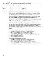
Страница 77: ...s timer and then energize any relay programmed as Fld Cont Aux relay NOTE Not used in Current control mode See Also Relay Output Configuration I O 05 07 P44 46 on Page 76 I O 9 P54 Analog Output Function LCD LED Displays I O Ain Trp Lvl 17 Off Range LCD LED Description Off 0 Disabled Default 0 200 Curr 1 Based on per cycle RMS values 0 150 Volt 2 Based on per cycle RMS values 0 100 Slip 3 Motor sp...

Страница 78: ...ceed 100 10V or 20mA Example 0 output 4mA 100 output 20ma See Also Analog Output Offset I O 11 P56 parameter on Page 78 I O 11 P56 Analog Output Offset LCD LED Displays I O Aout Offset 11 0 Range 0 99 Default 0 Description The analog output signal can be offset using the Analog Output Offset parameter A 50 offset outputs a 50 output 5V in the 10V case when 0 is commanded If the selected variable r...

Страница 79: ...ine voltage need not be present while stopped If no line is detected then the No Line alarm condition does not exist and the ready condition does exist If a start is commanded and there is no detected line voltage for the time period defined by this parameter then a noL No Line fault is declared In order to control an inline contactor program a relay as a Running relay NOTE This fault is different...

Страница 80: ...Also Local Source QST 04 P37 parameter on Page 61 Remote Source QST 05 P38 parameter on Page 61 I O 15 P57 Auto Start Selection LCD LED Displays I O Auto Start 15 Disabled Range LCD LED Description Disabled 0 When disabled the Start input must always transition from low to high for a start to occur Default Power 1 When set to Power a start will occur if the Start input is high while control power ...

Страница 81: ...ault LCD Meter 2 L1 L2 Volts 3 Voltage in L1 to L2 RMS L2 L3 Volts 4 Voltage in L2 to L3 RMS L3 L1 Volts 5 Voltage in L3 to L1 RMS Slip Percent 6 The percentage of rotor slip Phase Order 7 Phase rotation Line Freq 8 Line Frequency Analog Input 9 Analog Input Analog Out 10 Analog Output Run Days 11 Running time in days wraps at 2 750 days Run Hours 12 Running time in Hours and Minutes wraps at 24 0...

Страница 82: ...rameter FUN 03 P35 for Number of Turns The Hall Effect turns parameter sets the number of times the field power wire passes through the window of the Hall Effect current sensor Hall Effect Ratio Number of Turns FUN04 P36 Burden Resistance Ohms Current Low Current High 1000 1 6 100 ohm 0 5W 1 1 8 4 100 ohm 0 5W 1 9 12 2 100 ohm 0 5W 1 13 25 1 100 ohm 0 5W 1 26 50 2000 1 6 56 2 ohm 1W 1 5 35 4 56 2 ...

Страница 83: ...h the set phase rotation the controller displays an Alarm while stopped and faults if a start is attempted FUN 06 Rated RMS Voltage LCD LED Displays FUN Rated Volts 05 120 Vlt Range 100 110 120 200 208 220 230 240 340 350 380 400 415 440 460 480 500 525 575 600 660 690 800 1000 1140 Default 120 Description The Rated Voltage parameter sets the line voltage that is used when the controller performs ...

Страница 84: ...be allowed when operating in Power Factor Control Mode See Also Rated Power Factor FUN 07 P60 parameter on Page 84 FUN 09 P39 Control Type LCD LED Displays FUN Control Type 09 Field Ctl Range LCD LED Description Field Ctl FcT1 Brush type motor field controller See Brushtype control in Section 7 1 1 on Page 89 Brushless bruS Brushless type field controller See Brushless control in Section 7 1 2 on ...

Страница 85: ...Source QST 04 P36 parameter on Page 61 Remote Source QST 05 P37 parameter on Page 61 FUN 12 P50 Communication Timeout LCD LED Displays FUN Com Timeout 12 Off Range Off 1 120 Default Off Description The Communication Timeout parameter sets the time that the controller continues to run without receiving a valid Modbus request If a valid Modbus request is not received for the time that is set the con...

Страница 86: ...eter displays the MX2 SEP software version for hardware BIPC 300063 01 When calling Benshaw for service this number should be recorded so it can be provided to the service technician In addition to viewing the software version with this parameter the software version is also displayed on power up On the LED display the software version is flashed one character at a time on power up On the LCD disp...

Страница 87: ...e command resets the user run time meters back to zero 0 The Reflash Mode command puts the MX2 SEP into a reflash program memory mode The reflash mode can only be entered if the MX2 SEP controller is idle When the reflash mode is entered the MX2 SEP waits to be programmed The onboard LED display shows FLSH The remote display is disabled after entering reflash mode The MX2 SEP does not operate norm...

Страница 88: ...nored When a passcode is set and an attempt is made to change a parameter through the display keypad the UP and DOWN keys simply have no effect When a passcode is set and an attempt is made to change a parameter through Modbus the MX2 SEP returns an error response with an exception code of 03 Illegal Data to indicate that the register can not be changed LED Display The following steps must be perf...

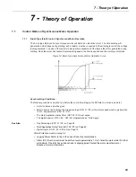
Страница 89: ...ons The following conditions must be true before the controller will apply the DC field to a brush type motor A start command must be given Motor slip must be less than the slip percentage CFN 01 P2 or the motor speed must be greater than 100 slip parameter CFN 01 P2 The Field Application delay Timer QST 02 P3 must expire The digital input s I O 01 03 P40 42 programmed as Field Apply See Also Slip...

Страница 90: ...med for Field Apply then the field will be applied when the input is energized If the Field Application Delay Timer is turned OFF and there is no digital input programmed then the field will be applied as soon as the run command is received See Also Slip Percentage CFN 01 P2 on Page 63 Field Application Delay Timer QST 02 P3 on Page 60 Digital Inputs I O 01 03 P40 42 on Page 75 Timeline 7 1 3 Curr...

Страница 91: ...PF at 50 load and the load is increased to 100 the motor PF will become lagging When MX2 SEP PF control is used the field current will be automatically increased so that the motor continues to operate at its defined PF level Closed loop PF control has multiple benefits 1 As the mechanical load changes on the motor the motor PF will change PF control will actively raise or lower the field excitatio...

Страница 92: ...ct input The SW1 switch must be set to the voltage loop configuration Figure 19 SW1 DIP Switch Settings The terminals for the Analog input on the MX2 card TB5 are as follows 2 input white 3 input black 4 Common black NOTE The analog input Hall Effect is a low voltage input maximum of 15VDC The input will be damaged if control power 115VAC or line power is applied to the analog input The terminals ...

Страница 93: ...7 Theory of Operation 93 Figure 21 Hall Effect Connections 0 700 Amps M COMMON 300063 01 xx MX CARD TB5 300044 02 01 SYNC CARD LEM GO TO LEM M Red White Black White Black BURDEN RESISTOR SEE P 35 FUN03 ...

Страница 94: ... MX 2 SEP Synchronous Controller User Manual 94 7 3 Simplified I O Schematics Figure 22 Digital Input Simplified Schematic Figure 23 Analog Input Simplified Schematic Figure 24 Analog Output Simplified Schematic ...

Страница 95: ...on the MX2 SEP The cable should contain two twisted pairs and have an overall shield Use one pair of conductors for the A and B signals Use the other pair of conductors for the Common signal The cable should adhere to the following specifications Conductors 2 twisted pair Impedance 100 Ohm to 120 Ohm Capacitance 16 pF ft or less Shield Overall shield or individual pair shields Examples of cables t...

Страница 96: ...his can cause damage to devices attached to the bus 7 4 6 Shielding The shield should be continuous from one end of the trunk to the other The shield must be tied to the RS 485 Common signal at one point and one point only If the shield is not tied to Common at any point or is tied to Common at more than one point then its effectiveness at eliminating noise is greatly reduced 7 4 7 Wiring Figure 2...

Страница 97: ...e with DB Braking Resistor The dynamic braking resistor is sized to 3X the motor FLA at rated motor voltage For example motor with stator rated 600VAC 380A rated 2 starts hour hot Resistor is sized to draw 1140A when 600VAC is applied 600 sqrt3 x 1140 0 304 ohms phase Y connected 600 1140 sqrt3 0 912 ohms phase delta connected The resistor must be capable of dissipating the energy in the rotating ...

Страница 98: ...RediStart MX 2 SEP Synchronous Controller User Manual 98 ...

Страница 99: ...th an IR tester megger 8 2 Preventive Maintenance 8 2 1 General Information Preventive maintenance performed on a regular basis will help to ensure that the controller continues to operate reliably and safely The frequency of preventive maintenance depends upon the type of maintenance and the installation site environment NOTE Preventive maintenance should always be performed by a trained technici...

Страница 100: ...correctly NOL or No Line is displayed and a start command is given it will fault in F28 No line voltage has been detected by the MX2 SEP when a start command is given Check input supply for inline contactor open disconnects open fuses open circuit breakers or disconnected wiring Verify that the SCR gate wires are properly connected to the MX2 SEP control board On medium voltage systems verify wiri...

Страница 101: ... wiring problem Check fan wiring Fan failure Replace fan Analog Output not functioning properly Voltage Current output switch SWI 2 not set correctly Set switch SW1 to give correct output Wiring problem Verify output wiring Analog Output Function parameter I O09 P53 set incorrectly Verify that the Analog Output Function parameter is set correctly Analog Output Offset and or Span parameters I O11 P...

Страница 102: ...ase power is connected to the L1 and L3 inputs Correct wiring if necessary Verify that the SCR gate wires are properly connected to the MX2 SEP control card F15 Input power not three phase Single phase power has been detected when the controller is expecting three phase power Verify that input power is three phase Correct wiring if necessary Verify that the SCR gate wires are properly connected to...

Страница 103: ... the controller If an inline contactor is being used verify that the setting of the Inline Configuration time delay parameter I O12 P49 allows enough time for the inline contactor to completely close Check input supply for open disconnects open fuses open circuit breakers or dis connected wiring Verify that the SCR gate wires are properly connected to the MX2 SEP control card On medium voltage sys...

Страница 104: ...heck motor for short circuits or ground faults Verify that the Current Setpoint QST01 P1 HD Sensor Ratio FUN03 P35 and HE Sensor Turns FUN04 P36 settings are correct Verify that the SCR gate wires are properly connected to the MX2 SEP Control card F56 BIST Undercurrent fault During powered BIST the measured field current is 10 or more below the reference current setpoint Check motor wiring for sho...

Страница 105: ...13 Check wiring between the remote network and the MX2 SEP control card Examine remote system for cause of communication loss F94 CPU Error SW fault Typically occurs when attempting to run a version of control software that is incompatible with the MX2 SEP control card hardware being used Verify that the software is a correct version for the MX2 SEP control card being used Consult factory for more...

Страница 106: ...measurements are within the above specifications 8 5 2 Voltage Extreme caution must be observed while performing these checks since the controller has lethal voltages applied while operating Using a DC voltmeter check between the gate leads for each SCR red and white twisted pair The voltage should between 0 5 and 2 0 volts 8 6 Field Discharge Resistor Sizing The induced field voltage product of i...

Страница 107: ...sensor is connected and positioned correctly and that the motor is connected Powered BIST mode can be entered by entering the appropriate value into the FUN 15 Miscellaneous Command user parameter NOTE The load wiring MUST be fully connected before starting the powered BIST tests Also the motor must be at rest stopped Otherwise the powered BIST tests will not function correctly NOTE Before using t...

Страница 108: ...The MX2 SEP will provide the programmed field current to the motor Measure the DC current with an ammeter to verify the proper current is being applied This level will be maintained for 60 seconds before moving to the next step or the start button can be pressed at any time to move on LCD Display BIST Mode LED Display BIST I x xA Field Test Step 4 LCD Display BIST Mode LED Display BIST Mode Tests ...

Страница 109: ...nto the aluminum heatsink Do turns until the SCR comes loose Remove the SCRs from the heatsink NOTE Do not loosen nut on indicator washer 6 This will change the clamping pressure of the clamp and the clamp will be defective 8 8 3 SCR Installation Coat the faces of the SCRs to be installed with a thin layer of EJC Electrical Joint Compound Place the SCRs onto the dowel pins The top SCR will have th...

Страница 110: ... under the nut s in the center of the loader bar becomes loose indicating the clamp is tight On the loader bars with two indicator washers it may be necessary to tighten or loosen one side of the clamp to get both indicator washers free 8 8 6 Tightening the SCR After the SCRs have been replaced conduct the resistance test as outlined in Section 8 5 Item Quantity Description 1 1 Loader Bar 2 2 Insu...

Страница 111: ...se This alarm exists while the MX2 SEP is stopped set to a three phase mode and single phase line voltage is detected If a start is commanded a Fault 15 occurs A21 Low Line L1 L2 This alarm exists while the MX2 SEP is stopped and low line voltage is detected If a start is commanded a Fault 21 may occur A22 Low Line L2 L3 This alarm exists while the MX2 SEP is stopped and low line voltage is detect...

Страница 112: ... is detected but the delay for the fault has not yet expired When the delay expires a Fault 38 occurs A47 Stack Over temperature Alarm This occurs when the stack thermal rises above 105 A60 External Alarm on DI 1 Input This occurs when a digital input is in its fault state but before the fault state has expired A61 External Alarm on DI 2 Input A62 External Alarm on DI 3 Input A71 Analog Input Leve...

Страница 113: ...rrent at Run Open Field during Run N N Y F40 Open Field at Start N N Y F41 Current at Stop N Y N F48 FS1 or FS2 Contactor Fault Y N N F49 Inline Contactor Fault Y N N F50 Control Power Low N N Y F51 Current Sensor Offset Error Y N F55 BIST Overcurrent fault N N N F56 BIST Undercurrent fault N N N F59 External Fault on Stack Input N N Y F60 External Fault on DIN 1 Input N N Y F61 External Fault on ...

Страница 114: ...RediStart MX 2 SEP Synchronous Controller User Manual 114 ...

Страница 115: ...tack O T Switch 3 Hall Effect Ratio 1000 1 2000 1 5000 1 MX2 SEP Card PC 300063 01 DV DT Board PC 300048 01 02 3 Control Power Transformers VA Voltage Specific Consult Factory SCRs BISCR5016x BISCR10016x BISCR13216x BISCR16116x BISCR25016x 3 Controller BISCR66018x BISCR88018x BISCR150018x 6 Controller Contactors RSC 9 6AC120 RSC 12 6AC120 RSC 18 6AC120 RSC 22 6AC120 RSC 32 6AC120 RSC 40 6AC120 RSC...

Страница 116: ...RediStart MX 2 SEP Synchronous Controller User Manual 116 ...

Страница 117: ...ntioned products comply with the following EU directives and Standards Safety UL 508 Standard for Industrial Control Equipment covering devices for starting stopping regulating controlling or protecting electric motors with ratings of 1500 volts or less Electromagnetic Compatibility EN 50081 2 Emissions Radiated Conducted EN 55011 05 98 A1 1999 EN 50082 2 Immunity Susceptibility which includes EN ...

Страница 118: ...RediStart MX 2 SEP Synchronous Controller User Manual 118 ...

Страница 119: ...0 A 09 Loss of Sync Bit 1 Not Used Reserved Bit 2 Not Used Reserved Bit 3 A 12 Low Line Frequency Bit 4 A 13 High Line Frequency Bit 5 A 14 Phase rotation not SPH Bit 6 A 15 Phase rotation not 3 Phase Bit 7 A 21 Low Line L1 L2 Bit 8 A 22 Low Line L2 L3 Bit 9 A 23 Low Line L3 L1 Bit 10 A 24 High Line L1 L2 Bit 11 A 25 High Line L2 L3 Bit 12 A 26 High Line L3 L1 Bit 13 A 27 Phase Loss Bit 14 Not Use...

Страница 120: ...uence Time R W 1 200 Sec 30108 40108 Pullout Mode R W 0 fault immediately 1 retry after delay 2 ride through 30109 40109 Pullout Delay Time R W 1 30 Sec 30110 40110 Resync Retry Attempts R W 1 10 30111 40111 Stop Mode R W 0 Coast 1 Dyn brake 30112 40112 Dynamic Brake Level R W 10 110 RFA 30113 40113 Dynamic Brake Time R W 1 180 Sec 30114 40114 Dynamic Brake Delay R W 1 50 0 1 Sec 30115 40115 Inchi...

Страница 121: ...40 30130 40130 Under Voltage Trip Enable R W 0 Disable 1 Enable 30131 40131 Under Voltage Trip Level R W 1 40 30132 40132 Over Under Voltage Delay Time R W 1 900 0 1 Sec 30133 40133 Phase Loss Delay Time R W 1 50 0 1 Sec 30134 40134 High Line Freq Trip Level R W 24 72 Hz 30135 40135 Low Line Freq Trip Level R W 23 71 Hz 30136 40136 High Low Line Freq Delay Time R W 1 900 0 1 Sec 30137 40137 Auto F...

Страница 122: ...d NFS 3 Running 4 Synced 5 Inching 6 Inching UTS 7 Alarm 8 Ready 9 Locked Out 10 Overcurrent 11 Undercurrent 12 Shunt Trip FS 13 Shunt Trip NFS 14 Field supply contactor 15 Field discharge resistor contactor 16 Field Contactor Aux 17 Dyn Braking 18 Cooling Fan 30152 40152 Relay 2 Function 30153 40153 Relay 3 Function 30154 40154 FCA Delay Enable R W 0 Disable 1 Enable 30155 40155 FCA Delay R W 1 9...

Страница 123: ... R 30603 40603 Fault Code 3rd Most Recent Fault Log Entry R 30604 40603 Fault Code 4th Most Recent Fault Log Entry R 30605 40603 Fault Code 5th Most Recent Fault Log Entry R 30606 40603 Fault Code 6th Most Recent Fault Log Entry R 30607 40603 Fault Code 7th Most Recent Fault Log Entry R 30608 40603 Fault Code 8th Most Recent Fault Log Entry R 30609 40603 Fault Code 9th Most Recent Fault Log Entry ...

Страница 124: ...0633 Voltage L1 3rd Most Recent Fault Log Entry R Vrms 30634 40634 Voltage L1 4th Most Recent Fault Log Entry R Vrms 30635 40635 Voltage L1 5th Most Recent Fault Log Entry R Vrms 30636 40636 Voltage L1 6th Most Recent Fault Log Entry R Vrms 30637 40637 Voltage L1 7th Most Recent Fault Log Entry R Vrms 30638 40638 Voltage L1 8th Most Recent Fault Log Entry R Vrms 30639 40639 Voltage L1 9th Most Rec...

Страница 125: ...3rd Most Recent Fault Log Entry R micro seconds 30664 40664 Line Period 4th Most Recent Fault Log Entry R micro seconds 30665 40661 Line Period 5th Most Recent Fault Log Entry R micro seconds 30666 40661 Line Period 6th Most Recent Fault Log Entry R micro seconds 30667 40661 Line Period 7th Most Recent Fault Log Entry R micro seconds 30668 40661 Line Period 8th Most Recent Fault Log Entry R micro ...

Страница 126: ...679 40679 Software State 9th Most Recent Fault Log Entry R 30681 40681 Motor Slip Most Recent Fault Log Entry R 30682 40682 Motor Slip 2nd Most Recent Fault Log Entry R 30683 40683 Motor Slip 3rd Most Recent Fault Log Entry R 30684 40684 Motor Slip 4th Most Recent Fault Log Entry R 30685 40685 Motor Slip 5th Most Recent Fault Log Entry R 30686 40686 Motor Slip 6th Most Recent Fault Log Entry R 306...

Страница 127: ...to Off or some value within a range many of the protection parameters for example there are two Modbus registers One is an enable register and the other sets the value within the range Bit 0 Ready 0 Initializing or Faulted and Braking or Faulted and Stopped or Lockout 1 Otherwise Bit 1 Running 0 Run Relay not energized 1 Run Relay energized Bit 2 Synced 0 Sync Relay not energized 1 Sync Relay ener...

Страница 128: ...RediStart MX 2 SEP Synchronous Controller User Manual 128 ...

Страница 129: ...Publication History Revision Date ECO 00 12 15 06 Initial Release 01 12 04 15 E4926 ...

Страница 130: ...ous Controller User Manual 130 BENSHAW 615 Alpha Drive Pittsburgh PA 15238 Phone 412 968 0100 Fax 412 968 5415 BENSHAW Canada 550 Bright Street Listowel Ontario N4W 3W3 Phone 519 291 5112 Fax 519 291 2595 ADVANCED CONTROLS DRIVES ...

Отзывы: