


89000109-002
xVue Touch Installation Manual
Rev 2
Page 4-5
© Honeywell International Inc. Do not copy without express permission of Honeywell.
For Use in Non-Certified Aircraft
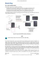
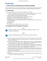
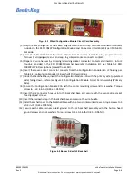
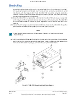
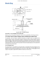
The bottom side of the J2 Backshell is illustrated in Figure 4-8, showing the ground connections for the
shielding. The wired configuration module in the J2 Backshell is illustrated in Figure 4-6.
Figure 4-6 Configuration Module Inside J2 Backshell
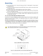
(1) Cut seven lengths of 22AWG wire (M22759/16-22-XX), per Table 4-1, to 2.5 ± 0.5 inches.
(2) Solder the seven lengths of wire per J-STD-001 to the Configuration Module CCA provided in the
KSD 100EXP Installation Kit -Configuration Module using Table 4-1 Configuration Module (J2
Backshell) Pin Descriptions.
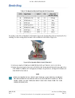
Table 4-1 Configuration Module (J2 Backshell) Pin Descriptions
J2 Pin
Signal Name
In/Out
CCA
Wire Color
(Recommended)
64
APM Master Out
Out
E1
Orange
65
APM Master In
In
E2
Blue
66
APM Clock
In
E3
Yellow
67
APM Chip Select
In
E4
Green
68
APM Write Protect
In
E5
White
69
APM Power
PWR
E6
Red
70
APM Return
GND
E7
Black
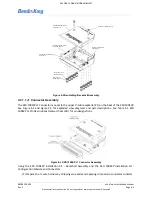
NOTE
WIRES ARE INSERTED IN THE CIRCUIT CARD THROUGH HOLES FROM THE SECONDARY
SIDE AND SOLDERED TO THE PRIMARY SIDE OF THE CARD (REFER TO FIGURE 4-7). VERIFY
SOLDER JOINTS DO NOT PROTRUDE MORE THAN 0.080 INCHES FROM THE CARD
SURFACE (PRIMARY SIDE).


