89000109-002
xVue Touch Installation Manual
Rev 2
Page 4-12
© Honeywell International Inc. Do not copy without express permission of Honeywell.
For Use in Non-Certified Aircraft
4.5 KG 71EXP Installation
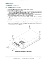
4.5.1 KG 71EXP Installation Procedures
(1) Ensure all wiring and power checks have been completed per Section 6.1.
(2) Ensure all power is removed from airplane.
(3) Locate and drill mounting holes using Figure A-6 KG 71EXP Dimensions and Center of Gravity and
Figure A-7 KG 71EXP Mounting Hole Pattern Diagram. The KG 71EXP must be mounted to an
avionics shelf or other rigid structure to reduce airplane vibration effects.
(4) Prepare mounting rivet nut locations as bonding points such that the bonding resistance conforms
to the guidelines listed in Section 3.10 Electrical Bonding Considerations.
(5) Apply conversion coating material conforming to MIL-C-81706 per AC 43-13-1B, to exposed metal
surfaces.
(6) Install four #10-32 rivet nuts, one at each of the four located mounting holes referenced in step
(3) and (4).
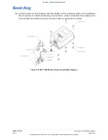
(7) Secure the KG 71EXP at the four mounting hole locations with the four #10-32 washer head
screws and four washers. Apply thread locking compound and install the mounting screws in the
following order (screw, washer, KG 71EXP unit, avionics shelf, rivet nut). Torque fasteners to 28 ±
2.8 in-lbs (3.16 ± 0.32 Nm). See Figure 4-14.
Figure 4-14 KG 71EXP ADAHRS Installation Diagram
P1

