


89000109-002
xVue Touch Installation Manual
Rev 2
Page 4-13
© Honeywell International Inc. Do not copy without express permission of Honeywell.
For Use in Non-Certified Aircraft
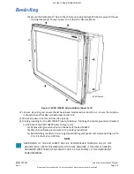
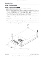
(8) Verify KG 71EXP is mounted within orientation parameters listed in Section 3.6.7.2.
(9) Verify that pitot-static drain ports are below the KG 71EXP to prevent condensation accumulation
and drainage into the unit.
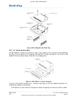
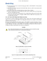
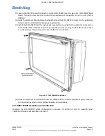
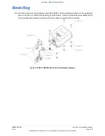
(10) On the KG 71EXP, apply thread-seal tape and attach the pitot line fitting and static line fitting to
the KG 71EXP, refer to Figure 4-15. Torque fittings to 50 in-lbs. (5.7 Nm) minimum, 60 in-lbs. (6.8
Nm) maximum - DO NOT OVER TIGHTEN.
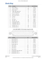
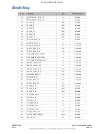
Figure 4-15 KG 71EXP Pressure Fitting Identification Diagram
(11) Verify the pitot and static pressure lines are correctly designated and clearly labeled with perma-
nently affixed labels at the attaching ends.
(12) Attach the pitot and static lines to their corresponding fitting on the KG 71EXP, 60 in-lbs. (6.8 Nm)
maximum - DO NOT OVERTIGHTEN. The KG 71EXP is labeled “PITOT” and “STATIC” at the fitting
sites to provide guidance.
(13) Attach the J71 connector to the KG 71EXP. Secure the two connector thumbscrews and torque to
4 ± 0.4 in-lbs (0.45 ± 0.05 Nm).
(14) Verify the electrical bond between the KG 71EXP and the airframe conforms to the guidelines
listed in Section 3.10 Electrical Bonding Considerations.
4.5.2 KG 71EXP Post Installation Unit Verification
Perform the following procedures of this manual to configure the KG 71EXP:
(1) Section 6.3 KG 71EXP Configuration (ADAHRS)
CAUTION
PITOT/STATIC DRAIN PORTS MUST BE PRESENT AND LOCATED THE LOWEST POINT OF THE
KG 71EXP SYSTEM INSTALLATION. A SECONDARY DRAIN OR SUMP BOTTLE MAY BE
REQUIRED TO PREVENT CONDENSATATION ACCUMULATION IN THE KG 71EXP.
CAUTION
PITOT AND STATIC LINES MUST BE INSTALLED TO THE CORRESPONDING FITTING. THE KG
71EXP WILL NOT FUNCTION CORRECTLY WITH IMPROPER INSTALLATION.