


Rev C, March 30, 2018
9
Manual Number 9019050
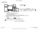
2.6 CABLE
HARNESS
Wire Gauge Selection
M27500-22TG2T14 (or equivalent) shielded twisted pair for both power/ground and data
lines. The ground wire should be attached to the airframe as close to the power source as
practicable.
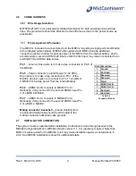
Pin Assignment Information
The MD32 is intended to connect directly to the MD302, requiring a single-point modification
to the installed cable harness. MD302 units updated with MOD 2 provide additional
connection options to allow for backup power to the MD32 from the internal battery, and to
accommodate a second ARINC 429 input so that the first input may remain connected to an
existing EFIS or ARINC data source.
Pin 1
– Ground. One option is to make a tee connection to Pin 6 of
the MD302.
Pin 5
– Power connects to aircraft power (7-32 VDC).
One option is to make a tee connection to Pin 1 of the
MD302. Another option is to connect to Pin 11 of a MOD
2 MD302 for backup power from the internal battery.
Pin 6
– ARINC Out B connects to MD302 Pin 13.
Optionally, it may connect to the second ARINC input Pin
4 of a MOD 2 MD302.
Pin 7
– ARINC Out A connects to MD302 Pin 12.
Optionally, it may connect to the second ARINC input Pin
9 of a MOD-2 MD302.
Mating connector backshell
– ground shield(s) from
the shielded twisted pair should be terminated to the
mating connector backshell (case ground).
2.7 INSTALLATION
COMPLETION
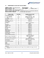
The system must be calibrated after installation. Calibration is done through access to the
MD302 Configuration Menu. MD302 software version 1.1.0 or greater is required. Note that
MOD 2 is not required for the MD302, but it may make installation easier as noted above in
2.6.2. See MD302 installation manual for additional details.
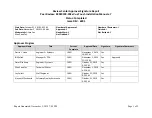
Pin # Description
1
Ground
2
Not Used
3
Reserved
4
Reserved
5
Power
6
ARINC Out B
7
ARINC Out A
8
Not Used
9
Not Used
Table
2.1
Connector
Pinout


