8 8
C H A N GE PARA METERS
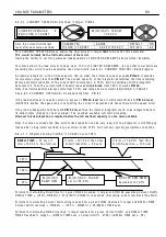
The conf
i
gurat
i
on of the PL/X po w er term
i
na
l
s us
i
ng L1/2/3 for stack and EL1/2/3 for f
i
e
l
d and
synchron
i
sat
i
on
i
s very versat
il
e. Th
i
s a
ll
o w s the ma
i
n contactor to be arranged
i
n numerous w ays.
1) EL1/2/3 permanent
l
y energ
i
sed w
i
th contactor on L1/2/3 g
i
ves very fast start
i
ng and a
ll
o w s the f
i
e
l
d to
rema
i
n energ
i
sed. (Requ
i
red for dynam
i
c brak
i
ng or to prevent condensat
i
on
i
n co
l
d c
li
mates).
2) EL1/2/3 and L1/2/3 energ
i
sed w
i
th ma
i
n contactor a
ll
o w s tota
l
e
l
ectr
i
ca
l
i
so
l
at
i
on of the motor.
3) Ma
i
n contactor on armature term
i
na
l
s for dynam
i
c brak
i
ng/
i
so
l
at
i
on of motor.
4) L1/2/3 may be used at a very
l
o w vo
l
tage. E. g. us
i
ng dr
i
ve as battery charger.
See 4.3 Ma
6.5.1.4 Prec
i
se stopp
i
ng
For very prec
i
se performance at the ramp end po
i
nts, e. g. stopp
i
ng,
i
t
i
s usefu
l
to be ab
l
e to RESET the
SPEED LO OP
i
ntegrator dur
i
ng the ramp
i
ng process. By ho
l
d
i
ng
i
t
i
n RESET dur
i
ng the ramp
i
ng process there
i
s no undes
i
rab
l
e
i
ntegra
l
term h
i
story to
i
ntefere w
i
th the
l
oop at the end of the ramp.
Th
i
s RESET can be ach
i
eved by connect
i
ng a JU MPER from 3 5)R A MPIN G FL A G to 7 3)SPEED IN T RESET.
In add
i
t
i
on, ensure that there are no sma
ll
demand s
i
gna
l
s enter
i
ng the speed
l
oop by d
i
sconnect
i
ng
un w anted
i
nputs to the SPEED REFEREN CE SU M MER and sett
i
o PIN 6 7 to zero.
A
l
so
i
t may be usefu
l
to have 6.7.7.1 SPEED PI A D APTIO N / Lo w break po
nt PIN 7 4 set to 0.2 % and
6.7.7.3 SPEED PI A D APTIO N / Lo w breakpo
n PIN 7 6 set
l
o w (e. g. 5.0 0) to m
i
n
i
m
i
se
the effects of tacho no
i
se at the stopp
i
ng po
i
nt.
See a
l
so 6.1 0.8.1 Lo w speed performance.
6.5.2 ST OP M O DE RA MP / Stop ramp t
i
me PIN 5 6
A standard 4 quadrant dr
i
ve can motor and brake
i
n both forw ard and reverse. It can a
l
so stop very qu
i
ck
l
y
by return
i
ng mechan
i
ca
l
rotat
i
ona
l
energy to the supp
l
y. It does th
i
s by effect
i
ve
l
y us
i
ng the motor as a
generator and the supp
l
y as a
l
oad to dump the energy
i
n.
A standard 2 quadrant dr
i
ve can on
l
y motor
i
n the forw ard d
i
rect
i
on, and cannot regenerate w hen stopp
i
ng.
Se
l
ected mode
l
s
i
n the PL 2 quadrant range have a spec
i
a
l
feature w h
i
ch a
ll
o w s them to regenerate w hen
stopp
i
ng. Th
i
s feature not on
l
y saves cons
i
derab
l
e amounts of energy but a
l
so e
li
m
i
nates the requ
i
rement for
dynam
i
c brak
i
ng res
i
stor systems.
See 3.3.1 Regenerat
6.5.3 ST OP M O DE RA MP / Stop t
i
me
li
m
i
t PIN 5 7
Th
i
s
i
s
i
n
i
t
i
ated by the start
i
nput go
i
ng
l
o w .
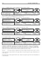
ST OP M O DE RA MP 3
5 6)ST OP RA MP TIME
5 6)ST OP RA MP TIME
1 0.0 SE C S
PAR A ME TER
RA N GE
DEF A ULT
PIN
ST OP R A MP TIME
0.1 to 6 0 0.0 secs
1 0.0 secs
5 6
Sets the 1 0 0 - 0 % do w n ramp
t
i
me
i
n norma
l
stop mode
R
R
ST OP M O DE RA MP 3
5 7)ST OP TIME LIMIT
5 7)ST OP TIME LIMIT
6 0.0 SE C S
PAR A ME TER
RA N GE
DEF A ULT
PIN
ST OP TIME LIMIT
0.0 to 6 0 0.0 secs
6 0.0 secs
5 7
Sets the max t
i
me
li
m
i
t before
contactor drop out
i
n stop mode
Содержание PLX
Страница 2: ...2 Contents ...
Страница 202: ......


