background image

C H A N GE PARA METERS 


7 3


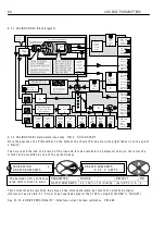
6.2.2  RUN M O DE R A MPS / Ramp output mon

i

tor   PIN 2 1 

Th

i

s mon

i

tor

i

ng  w

i

ndo w  

i

s ab

l

e to branch hop to 6.2.1 6 RUN  M O DE R A MPS / Ramp

i

ng f

l

ag   PIN 3 5. 

Note that the RUN M O DE RA MP may be act

i

ve  w hen the un

i

i

i

n stop mode. See 6.2.1 RUN M O DE R A MPS 

/ B

l

ock d

i

agram 

i

nc

l

ud

i

ng J O G. 

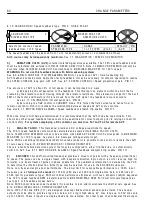
6.2.3  RUN M O DE R A MPS / For w ard up t

i

me   PIN 2 2 


6.2.4  RUN M O DE R A MPS / For w ard do w n t

i

me   PIN 2 3  


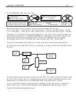
6.2.5  RUN M O DE R A MPS / Reverse up t

i

me   PIN 2 4 


6.2.6  RUN M O DE R A MPS / Reverse do w n t

i

me   PIN 2 5 


RUN M O DE R A MPS          3 

2 4)RE V ERSE UP TIME 

2 4)RE V ERSE UP TIME 
            1 0.0 SE C S 

PAR A ME TER 

RA N GE 

DEF A ULT 

PIN

RE V ERSE UP TIME 

 0.1  to 6 0 0.0 seconds   1 0.0 secs 

2 4 

Sets the ramp t

i

me for 0-1 0 0 %  

of the reverse -ve reference. 

R

R

RUN M O DE R A MPS          3 

2 1)RA MP  OP M O NIT OR 

2 1)RA MP  OP M O NIT OR


                  0.0 0 %  

PAR A ME TER 

RA N GE 

PIN 

RA MP  OP  M O NIT OR 

         + /-1 0 0.0 0 %  

2 1 

A

ll

o w s the output 

l

eve

l

 of the ramp b

l

ock 

to be mon

i

tored. 

R

R

RUN M O DE R A MPS          3 

2 2)F OR W ARD UP TIME 

2 2)F OR W ARD UP TIME 
            1 0.0 SE C S 

PAR A ME TER 

RA N GE 

DEF A ULT 

PIN

F ORW ARD UP TIME 

 0.1  to 6 0 0.0 seconds   1 0.0 secs 

2 2 

Sets the ramp t

i

me for 0-1 0 0 %  

of the forw ard  + ve reference. 

R

R

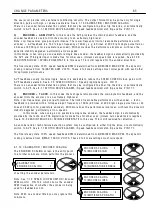
RUN M O DE R A MPS          3 

2 3)F OR W ARD D O W N  TIME 

2 3)F OR W ARD D O W N  TIME 
            1 0.0 SE C S 

PAR A ME TER 

RA N GE 

DEF A ULT 

PIN

F ORW ARD D O W N TIME 

 0.1  to 6 0 0.0 seconds   1 0.0 secs 

2 3 

Sets the ramp t

i

me for 1 0 0-0 %  

of the forw ard  + ve reference. 

R

R

RUN M O DE R A MPS          3 

2 5)RE V ERSE D O W N TIME 

2 5)RE V ERSE D O W N TIME 
             1 0.0 SE C S 

PAR A ME TER 

RA N GE 

DEF A ULT 

PIN

RE V ERSE D O W N TIME 

 0.1  to 6 0 0.0 seconds   1 0.0 secs 

2 5 

Sets the ramp t

i

me for 1 0 0-0 %  

of the reverse -ve reference. 

R

R

Содержание PLX

Страница 1: ...1 Part 1 PL PLX Digital DC Drive Part 2 Application Blocks Part 3 High Power Modules PL PLX Digital DC Drive Part 1 HG102633 v5 15i ...

Страница 2: ...2 Contents ...

Страница 3: ...TION BLO CKS Part 3 PL X 275 980 from 650 A to 2250 A SERIAL CO MMS and ST A CK DRIVER All also available to download from the internet at w w w sprint electric com 1 Table of contents 1 Table of contents 3 2 Warnings 13 2 1 General Warnings 13 2 2 Warnings and Instructions 14 2 3 General Risks 15 2 4 Summary of further W ARNINGS 16 3 Introduction and Technical Data 19 3 1 Introduction 20 3 2 How ...

Страница 4: ...n continued 54 5 2 7 Full menu diagram Block OP and Fieldbus configs Drive personality and Conflict Help 55 5 3 Archiving PL X recipes 56 6 CHANGE PARAMETERS 57 6 1 CH ANGE PARA METERS C ALIBRA TION 59 6 1 1 C ALIBRA TION Block diagram 60 6 1 2 C ALIBRA TION Rated armature amps PIN 2 QUICK ST ART 60 6 1 3 C ALIBRA TION Current limit PIN 3 QUICK ST ART 61 6 1 4 C ALIBRA TION Rated field amps PIN 4 ...

Страница 5: ...ISED PO T RA MP MP preset PIN 52 83 6 4 7 MOTORISED PO T RA MP MP Preset value PIN 53 84 6 4 8 MOTORISED PO T RA MP MP memory boot up PIN 54 84 6 5 CH ANGE PARA METERS STOP MODE RA MP 85 6 5 1 STOP MODE RA MP Block diagram 85 6 5 1 1 Block diagram of contactor control 86 6 5 1 2 Speed profile when stopping 87 6 5 1 3 Contactor drop out 87 6 5 1 4 Precise stopping 88 6 5 2 STOP MODE RA MP Stop ramp...

Страница 6: ...e current loop control terms manually 105 6 8 13 CURRENT CONTROL 4 quadrant mode enable PIN 96 105 6 8 14 CURRENT CONTROL Speed bypass current reference enable PIN 97 105 6 9 CH ANGE PARA METERS FIELD CONTROL 106 6 9 1 FIELD CONTROL Block diagram 107 6 9 2 FIELD CONTROL Field enable PIN 99 108 6 9 3 FIELD CONTROL Voltage output PIN 100 108 6 9 4 FIELD CONTROL Field proportional gain PIN 101 108 6 ...

Страница 7: ... PIN 136 126 7 2 5 ARM I LO OP MONITOR Lower current limit monitor PIN 137 126 7 2 6 ARM I LOOP MONITOR Actual prevailing upper lower current limits PINs 138 139 127 7 2 7 ARM I LO OP MONITOR Overload limit monitor PIN 140 127 7 2 8 ARM I LO OP MONITOR At current limit flag PIN 141 127 7 3 DIA GNOSTICS FLD I LO OP MONITOR 128 7 3 1 FLD I LO OP MONITOR Field demand monitor PIN 143 128 7 3 2 FLD I L...

Страница 8: ...8 1 11 14 DRIVE TRIP MESSA GE Short circuit digital outputs 146 8 1 11 15 DRIVE TRIP MESSA GE Bad reference exchange 146 8 1 11 16 DRIVE TRIP MESSA GE Cannot autotune 147 8 1 11 17 DRIVE TRIP MESSA GE Autotune quit 147 8 1 11 18 DRIVE TRIP MESSA GE Contactor lock out 147 8 1 11 19 DRIVE TRIP MESSA GE Warning flags 147 9 SELF TEST MESSAGE 148 9 1 1 SELF TEST MESSA GE Data corruption 148 9 1 2 SELF ...

Страница 9: ...icting GOTO connections 166 12 1 4 2 Application blocks PIN table 166 13 CONFIGURATION 167 13 1 CONFIGURA TION menu 168 13 1 1 PL PILOT configuration tool 168 13 2 Configurable connections 169 13 2 1 Key features of GOTO window 170 13 2 2 Key features of GET FROM window 170 13 2 3 Summary of GOTO and GET FROM windows 171 13 2 4 JUMPER connections 171 13 2 5 Block Disconnect PIN 400 171 13 2 6 Hidd...

Страница 10: ...4 Make output GET FROM source connection 185 13 6 1 6 DIO X SETUP DIO 1 2 3 4 Make input GOTO destination connection 185 13 6 1 7 DIO X SETUP DIO 1 2 3 4 Input high value PINs 275 281 287 293 185 13 6 1 8 DIO X SETUP DIO 1 2 3 4 Input low value PINs 276 282 288 294 186 13 6 1 9 Default connections for DIO1 2 3 4 186 13 6 1 10 DIO1 2 3 4 Internal output result PINs 685 6 7 8 186 13 7 CONFIGURA TION...

Страница 11: ...ensions PL X 185 265 210 14 7 1 1 Mounting PL X 185 265 210 14 7 1 2 Venting models PL X 185 265 using back panel aperture 211 14 7 1 3 Venting models PL X 185 265 using standoff pillars 211 14 8 Line reactors 212 14 9 Wiring instructions 213 14 9 1 Wiring diagram for A C supply to L1 2 3 different to EL1 2 3 E g Low voltage field 213 14 10 Terminal tightening torques 214 14 11 Installation guide ...

Страница 12: ...12 Contents There is a system block diagram at the back of the manual also available for downloading from the web site w w w sprint electric com www bardac com ...

Страница 13: ...portant aid to SAFETY and productivity SAFETY a wareness not only reduces the risk of accidents and injuries in your plant but also has a direct impact on improving product quality and costs If you have any doubts about the SAFETY of your system or process consult an expert immediately Do not proceed without doing so HEALTH AND SAFETY AT WORK Electrical devices can constitute a safety hazard It is...

Страница 14: ...ental conditions of installation for safe and reliable operation Never perform high voltage resistance checks on the wiring without first disconnecting the product from the circuit being tested STATIC SENSITIVE This equipment contains electrostatic discharge ESD sensitive parts Observe static control precautions when handling installing and servicing this product THESE WARNINGS AND INSTRUCTIONS AR...

Страница 15: ...sk of injury NOTE During a power loss event the product will commence a sequenced shut down procedure and the system designer must provide suitable protection for this case MAINTENANCE Maintenance and repair should only be performed by competent persons using only the recommended spares or return to factory for repair Use of unapproved parts may create a hazard and risk of injury WHEN REPLACING A ...

Страница 16: ...rements Follow the instructions and all the above requirements are under the control of the PL X automatically See 4 2 Main Contactor operation It may be necessary for installations to have over riding external independent systems for de energising the main contactor In this case it is recommended that the CSTOP terminal be opened 100mS in advance of the main contacts opening Failure to achieve th...

Страница 17: ...otation above base speed Failure to do so may result in mechanical failure with disastrous consequences If however your desired maximum rpm is low compared to the base rpm then you need to be a ware of the heat dissipation in the motor at full torque Use motor force venting if necessary See 6 1 6 C ALIBRA TION Desired max rpm PIN 6 QUICK ST ART WARNING Do not use AVF feedback mode with field weake...

Страница 18: ...w 117 ZERO INTLK SPD It may be necessary to increase 117 ZERO INTLK SPD to ensure tripping See 8 1 8 1 ST ALL TRIP MENU Stall trip enable PIN 178 After a DATA CORRUPTION message Check that the calibration parameters and drive personality Iarm burden value are correct See 9 1 1 SELF TEST MESSA GE Data corruption Warning the 24V supply on pin 2 may damage your PC or other instrument If in doubt do n...

Страница 19: ...nerative stopping with PL models 22 3 3 2 Supply voltages required for all models 22 3 3 3 Control terminals electrical specification 24 3 4 Control terminals overvie w 25 3 4 1 General requirements 25 3 4 2 Digital inputs and outputs 25 3 4 3 Analogue inputs 26 3 4 4 Analogue tachogenerator input 27 3 4 5 Signal test pins 27 3 5 Control terminal default functions 27 3 5 1 Run Jog Start Cstop 29 3...

Страница 20: ... feedback remains identical to the current demand during normal operation This inner loop monitors the armature current and delivers more current or less current as required The outer speed loop works in the same way as the inner current loop but uses different parameters In the above example the demand is provided by the user in the form of a speed reference and the speed feedback is derived from...

Страница 21: ...ter values may be listed out on a printer Parameters that have been altered from the default are identified in the listing They may also be sent to or received from another unit or computer 12 The unit contains standard special applications blocks that are normally switched off unless activated by the user These include signal processors PIDs etc They do not take part in the prime control of the m...

Страница 22: ...lectronic regenerative stopping See 6 5 2 STOP MODE RA MP Stop ramp time PIN 56 3 3 2 Supply voltages required for all models The supplies provided must be suitable for the motor employed Main 3 phase 50 6OHz Any supply from 12 to 480V A C 10 for armature power Auxiliary 3 phase 50 6OHz Any supply from 100 to 480V A C 10 for field power Control 1 phase 50 60Hz Any supply from 110 to 240V A C 10 50...

Страница 23: ...ture 0 40C ambient operating temperature 35C for PL X900 and PL X980 Derate by 1 per Deg C above 40C up to 50C max storage 5C 55C Protect from direct sunlight Ensure dry corrosive free environment Humidity 85 Relative humidity maximum Note Relative humidity is temperature dependent do not allow condensation Atmosphere Non flammable non condensing Pollution Degree 2 Installation cat 3 Altitude Dera...

Страница 24: ...digital outputs the spec is the same as DOP1 3 DIO4 21 DIGIT AL OUTPUTS 3 outputs for 4 more outputs with this spec use DIO1 2 3 4 DOP1 22 Short circuit protected Range 22 to 32 Volts for OP high DOP2 23 DOP1 DOP3 Over temperature and over voltage protected to 50V DOP3 24 Each output can deliver up to 350mA Total for all outputs of 350mA This spec also applies to DIO1 2 3 4 when they are programme...

Страница 25: ...tputs 4 analogue outputs This is achieved by allowing the 8 analogue inputs to also be used as digital inputs and 4 digital outputs that can be independently programmed as inputs The analogue outputs do not usually need to be so numerous as soft ware connections can be made by the user Even so 4 analogue outputs are available of which 3 are programmable The analogue outputs are individually short ...

Страница 26: ... to the 24V output which also has its own 50mA capability giving a maximum total to the 24V output of 400mA if no digital output is being used This shows the output configuration for each digital output DOP1 to DOP3 and DIO1 to DIO4 The digital outputs are also designed to be OR d together or with outputs from other drives if desired This is sometimes useful if an external event must wait for seve...

Страница 27: ...ain feedback signals The Iarm signal is an attenuated unfiltered inverted version of terminal 29 and may be used to observe the current response of the PL X See 13 13 3 DRIVE PERSONALITY Maximum current response PIN 678 See 13 4 1 AN ALO G OUTPUTS A OP4 Iarm output rectify enable PIN 250 Signal sign and amplitude is 0 to 2V linear output for 0 to 100 model rating current inverted for unrectified m...

Страница 28: ...nalogue Output AOP1 T10 0 to 10V linear output for 0 to 100 speed feedback Output current capability 5mA max Short circuit protection to 0V A OP1 or 2 or 3 must not be simultaneously shorted to 0V Programmable Uni polar or Bi polar output mode Total Speed Reference Analogue Output AOP2 T11 0 to 10V linear output for 0 to 100 total speed reference Output current capability 5mA max Short circuit pro...

Страница 29: ...f the machine These devices have a low resistance typically 200 Ohm up to a reference temperature 125 C Above this temperature their resistance rises rapidly to greater than 2000 Ohms Motor over temperature sensors should be connected in series between terminals T30 and T36 A motor over temperature alarm will be displayed if the external resistance between T30 and T36 exceeds 1800 Ohms 20O Ohms Se...

Страница 30: ...ow and mode select high then start going high acts as the cra wl control See 6 3 5 JOG CRA WL SLA CK Jog mode select PIN 42 The cra wl uses the run mode ramp times to accelerate and the Stop mode ramp times to stop Coast stop main contactor control Digital input CSTOP T34 With a high input the controller operates normally When the Coast Stop is at zero volts or open circuit the main contactor is o...

Страница 31: ...Motorised pot simulator preset enable Digital Input UIP7 T7 Motorised pot simulator Increase Digital Input UIP8 T8 Motorised pot simulator Decrease Digital Input UIP9 T9 Speed feedback Analogue Output A OP1 T10 Total speed reference Analogue Output A OP2 T11 Total current demand Analogue Output A OP3 T12 O V terminal Protective clean earth connected here 0V T13 Spare input Digital Input DIP1 T14 M...

Страница 32: ... supply loss may simultaneously be recognised by port 2 and port 3 A total supply loss to the installation will occur on all 3 ports simultaneously See 8 1 11 MO TOR DRIVE ALARMS DRIVE TRIP MESSA GE A loss on port 1 will be recognised below approx 80V A C See also 9 1 10 SELF TEST MESSA GE Internal error code for details of dips on port 1 Effects of supply loss or dips The armature and field curre...

Страница 33: ...re Always check safety systems thoroughly and observe local safety codes The suggested strategy is to start in the safest possible mode of operation and progressively exercise each element of the system until full functionality has been achieved This chapter is a step by step approach up to 4 in this list 1 Check installation and supplies L1 2 3 EL1 2 3 and control supply and all safety systems 2 ...

Страница 34: ...r control board arranged as 3 blocks of 12 Terminals 2 12 14 24 and 31 are programmable Their default function is shown here Speed ref Current ref Ramped Speed Setpoint Lo wer Current Clamp Main Upper Current Clamp Motorised Pot Preset Motorised Pot Increase Motorised Pot de crease Speed Feedback 0 V Terminal Tot al Spe ed Re ference Total Current Demand Speed Ref erence 0 V Terminal Zero ref eren...

Страница 35: ... opened 100mS in advance of the main contacts opening Failure to achieve this may result in damage to the unit Note If the users main contactor has a closing time delay of greater than 75mS then it is essential that steps are taken to delay the release of armature current until the main contact has closed 1 Insert an auxiliary normally open contact on the main contactor in series with the RUN inpu...

Страница 36: ...C semiconductur fuse in the armature circuit This fuse should open before the thyristor junction fails Question What if the grid system fails totally Answer This is not as bad as losing the contactor coil supply Most installations naturally have other loads that provide a safe discharge path before the contactor opens Question What if the grid system fails for a fe w cycles Brown outs Answer The P...

Страница 37: ...hout additional measures The field standby level may not be set to a low enough level by the user and could cause overheating of the field winding Phase forward may occur before contactor has closed causing fault current Time delay from ST ART command to phase forward is 75mS 4 3 2 Main contactor isolating AC stack and auxiliary supplies Advantages The field winding is electromechanically isolated...

Страница 38: ...vantages The field winding is not electromechanically isolated by the main contactor which may contravene safety codes without additional measures The field standby level may not be set to a low enough level by the user and could cause overheating of the field winding The A C supply is permanently connected to the PL X unless further provision is made to isolate the supplies Note The armature must...

Страница 39: ...regeneration during the stopping sequence an external latching circuit must be employed to control the STOP ST ART contacts T47 48 cannot be used and the RUN input is not controlled from the ST ART terminal See 4 3 5 Using pushbuttons for STOP ST ART With ramp to stop jog and slack take up See 6 5 CHA NGE PARA METERS STOP MODE RA MP T47 LA T1 T34 CSTOP T33 START T35 24V T46 CON2 T45 CON1 STOP ST A...

Страница 40: ...a JOG function when the drive is stopped ST ART open and as the SLA CK 1 take up function when the drive is running ST ART closed With the STOP button held open no running button is operative JOG SLA CK or ST ART T47 LA T1 T34 CSTOP T33 START T35 24V T46 CON2 T45 CON1 Contactor COIL SUPPLY CO AST STOP Must be high prior to ST ART M AIN CONT A CTOR INTERN AL CONT A CTS Internal contacts 24V coil en...

Страница 41: ...nal to control and ground Disconnect the drive for wiring tests using a megger Control terminals are plug in type 8 The engineering standards employed must comply with any local national or international codes in force Safety requirements take priority 9 If the load regenerates or regenerative braking is employed then a DC rated armature fuse with the correct I2 t rating in series with the motor a...

Страница 42: ...sen limits may be saved and will remain unaltered unless you wish to re calibrate There is also the choice of using a password to prevent unauthorised re calibration The unit automatically knows the model armature current ratings and will prevent setting of armature current in excess of the model rating See 13 13 4 DRIVE PERSONALITY Armature current burden resistance PIN 680 The parameters that wi...

Страница 43: ...atch your motor it is time to apply 3 phase power for the first time to establish correct functioning of the main contactor and that the field current is correct Remember that there should be a fire bar inserted in the armature circuit to protect against fault currents See 4 2 Main Contactor operation and 7 3 DIA GNOSTICS FLD I LOOP MONITOR Once you have established correct functioning of the main...

Страница 44: ...different motors See 6 1 17 C ALIBRA TION Motor 1 or 2 select PIN 20 The default values for the passive motor this is motor 2 from the factory are set at a level to suit very small motors Making these values the active set during a system test with a small motor will save time altering and then re setting the control terms on motor 1 The dynamic performance of the test motor by making the default ...

Страница 45: ... windows 48 5 1 7 Finding the soft ware version number of the unit 48 5 2 ENTRY MENU 4 8 5 2 1 Full menu diagram Change parameters 49 5 2 2 Full menu diagram Change parameters continued 50 5 2 3 Full menu diagram Diagnostics 51 5 2 4 Full menu diagram Motor drive alarms serial links and display functions 52 5 2 5 Full menu diagram Application blocks and configuration 53 5 2 6 Full menu diagram Con...

Страница 46: ...per line of characters If you hold the left key down you will quickly arrive back at the default diagnostic windows The level number is displayed at the right hand end of the top line As well as travelling around the tree structure the keys perform other functions These are as follows PRESS RIGHT KEY FOR ENTRY MENU LEVEL 1 LEFT exit to previous menu level DO WN decrease RIGHT enter next menu level...

Страница 47: ... and it is easier to start again If all 4 keys are held down during the application of the control supply then the drive will automatically display the default parameters and connections EXCEPT those in the CALIBRATION menu and 100 FIELD VOLTS OP for MOTOR 1 and MOTOR 2 and 680 Iarm BURDEN OHMS These parameters remain as previously calibrated to prevent accidental de calibration when restoring def...

Страница 48: ...ll up and down After tapping the right key to proceed to the next level you can travel up and down the level using the up and down keys The menus are circular so you can travel up or down to reach your desired destination The menus are designed so that the most frequently used windows are closest to the entry points There are 2 styles of menu that can be selected using DISPLA Y FUNCTIONS REDUCED a...

Страница 49: ... Ramping threshold Ramping flag MOTORISED POT RAMP Output monitor Up time Down time Up command Down command Maximum clamp Minimum clamp Preset Preset value Memory boot up STOP MODE RAMP Stop ramp time Stop time limit Live delay mode Drop out speed SPEED REFERENCE SUMMER Internal speed reference 1 Speed reference 2 Speed current ref 3 mon Ramped speed reference 4 Speed current reference 3 sign Spee...

Страница 50: ...Base rated RPM Desired max RPM Zero speed offset Max tacho volts Speed feedback type Encoder scaling IR compensation Field current fb trim Arm volts trim Analog tacho trim Rated arm volts EL1 2 3 rated a c Motor 1 2 select ENCODER SCALING Quadrature enable Encoder lines Motor encoder speed ratio Encoder sign CURRENT CONTROL Current clamp scaler Current overload I dynamic profile Dual current clamp...

Страница 51: ...ad limit monitor At current limit flag FIELD CURRENT LOOP MONITOR Field demand monitor Field current monitor Field current amps monitor Field angle of advance Field active monitor DIGITAL IO MONITOR UIP 23456789 DIP 1234 1234 DIO DOP 123TRJSC CIP armature bridge flag Drive start flag Drive run flag Running mode monitor BLOCK OUTPUT MONITOR Ramp output monitor Motorised pot output monitor Reference...

Страница 52: ...AL LINKS Section 10 RS232 port 1 RS232 PORT 1 Port 1 baud rate Port 1 function Parameter exchange Reference exchange Port 1 comms link PARAMETER EXCHANGE Drive transmit Drive receive Menu list to host REFERENCE EXCHANGE Ref exch slave ratio Ref exch slave sign Ref exch slave monitor Ref exch master monitor Get from DISPLAY FUNCTIONS Section 11 Reduced menu enable Password control Language select S...

Страница 53: ...witch 3 C O Switch 4 Note Further application blocks may be available Please refer to the separate APPLICA TION BLOCKS MA NUAL for details on the specification and use of the apps blocks UNIVERSAL INPUTS UIP2 setup UIP3 setup UIP4 setup UIP5 setup UIP6 setup UIP7 setup UIP8 setup UIP9 setup UIP SETUP 2 9 UIP input range UIP input offset UIP calibration ratio UIP maximum clamp UIP minimum clamp UIP...

Страница 54: ... input high value DIP input low value Goto DOP SETUP 1 3 DOP rectify enable DOP threshold DOP invert mode Get from STAGING POSTS Digital post 1 Digital post 2 Digital post 3 Digital post 4 Analog post 1 Analog post 2 Analog post 3 Analog post 4 JUMPER CONNECTIONS Jumper 1 Jumper Jumper Jumper Jumper Jumper Jumper Jumper Jumper 16 DIGITAL INPUTS DIP1 setup DIP2 setup DIP3 setup DIP4 setup Run input...

Страница 55: ...ce 2 Speed current ref 3 mon Ramped speed reference 4 Speed current reference 3 sign Speed current reference 3 ratio Maximum positive speed reference Maximum negative speed reference Speed proportional gain Speed integral time constant Current clamp scaler Current proportional gain Current integral gain Current discontinuity 4 Quadrant mode Field enable Field volts output Standstill enable Zero in...

Страница 56: ...vantages Very compact file Complete record of every parameter including motor and model ratings Easy to archive and identify files Disadvantages Not editable Will overwrite 680 Iarm BURDEN OHMS 2 RA TED ARM A MPS and 4 RA TED FIELD A MPS which will then need re entering for models and or motors of different rating to source file 2 PL PILOT running on windows See 10 2 5 Parameter exchange using ASC...

Страница 57: ...6 3 CH ANGE PARA METERS JOG CRA WL SLA CK 77 6 4 CH ANGE PARA METERS MOTORISED PO T RA MP 81 6 5 CH ANGE PARA METERS STOP MODE RA MP 85 6 6 CH ANGE PARA METERS SPEED REF SUMMER 90 6 7 CH ANGE PARA METERS SPEED CONTROL 92 6 8 CH ANGE PARA METERS CURRENT CONTROL 97 6 9 CH ANGE PARA METERS FIELD CONTROL 106 6 10 CH ANGE PARA METERS ZERO INTERLO CKS 113 ...

Страница 58: ...ain If all 4 keys are held down during the application of the control supply then the drive will automatically refer to the default parameters and internal connections However parameters that are used to match the motor to the drive are not affected by restoring the defaults This includes all those in the CALIBRATION menu and 100 FIELD VOLTS OP for MOTOR 1 and MOTOR 2 and 680 Iarm BURDEN OHMS Thes...

Страница 59: ...important to understand how it is affected by a connection to another source In this case the value is solely determined by the source and by looking at the parameter you can use it as a diagnostic monitor of that source The parameter value may only be re entered if the connection from the source is first removed Note Bold windows are used for QUICK START PIN 3 CH ANGE PARA METERS 2 C ALIBRA TION ...

Страница 60: ...und motor Tachogenerator And or encoder F F A A _ Data Plate MOTOR DA T APLA TE Max rated arm amps Max rated arm volts Max rated field amps Max rated field volts Base rated RPM TA CHO DA TAPLA TE Volts 1000 RPM Type Bipolar Rectified A C DC ENCODER DA TAPLA TE Lines per revolution Isolated sensors for arm current and PL X A A terminal V Av IA Rated field Amps PIN 4 PIN 144 Field Amps Feedback PIN ...

Страница 61: ...esistance of the field winding after allowing it to reach full working temperature then using the following equation Field current Field dataplate volts Resistance in Ohms Alternatively if you know the rated field voltage you can go to the CHANGE PARA METERS FIELD CONTROL menu and select the 100 FIELD V OLTS OP clamp parameter Adjust the field output voltage to the dataplate value as a of the appl...

Страница 62: ... of the motor if necessary 6 1 7 C ALIBRA TION Zero speed offset PIN 7 This is useful if your speed feedback is derived from an external amplifier which may have a small offset If this parameter is adjusted un necessarily then it will appear as an offset on the speed feedback See 7 1 10 SPEED LO OP MONITOR Speed feedback monitor PIN 131 C ALIBRA TION 3 5 BASE RA TED RPM 5 BASE RA TED RPM 1500 RPM ...

Страница 63: ...lts for positive speed demand For tacho volts which exceed 200 V full scale it is necessary to provide an external resistor dropper net work as follows The net work shown will allow full scale voltages up to 400 Volts The number scrolled in the window should be set to half the full scale tacho volts Appropriate measures must be taken to dissipate the heat from the dropper resistors The total power...

Страница 64: ... to speed The 100 speed feedback volts must be calculated and entered into 8 M A X T A CHO V OLTS Note 130 MO TOR RPM MON will only be accurate when 8 M A X T A CHO V OLTS corresponds to 6 DESIRED M A X RPM for 100 speed See also 3 4 4 Analogue tachogenerator input Note With an additional bi directional shaft mounted encoder it is possible to lock and or orientate the shaft at zero speed See 6 10 ...

Страница 65: ...e it is advisable to reduce the SPEED CONTROL loop gains with A VF feedback selected See 6 7 4 SPEED CONTROL Speed proportional gain PIN 71 There is an encoder failure detection system that may be configured to either trip the drive or automatically switch to A VF See 8 1 1 MOTOR DRIVE ALARMS Speed feedback mismatch trip enable PIN 171 4 ENCODER TACHO In this mode the tachogenerator provides the m...

Страница 66: ...trains for good phase holding and no interference Do this with the drive rotating to 100 speed using A VF as the feedback source Low frequency feedback may give poor results at low speed Hence for encoders or other types of pick up providing less than 15KHz at full speed it is recommended that mode 3 or mode 4 combined feedback type is utilised See 6 1 9 C ALIBRA TION Speed feedback type PIN 9 QUI...

Страница 67: ...ote An encoder may be input and used for other tasks instead of feedback On hidden PIN 709 MOTOR RPM is the encoder feedback scaled to 100 6 DESIRED M A X RPM It is also scaled by 12 MO T ENC SPD RA TIO which acts as a pure multiplying factor Both 132 ENCODER RPM and PIN 709 MOTOR RPM are purely encoder signals that work independently of the type of feedback selected They both read zero with no pu...

Страница 68: ...ack has been determined using this trim the DIA GNOSTICS menu can be used to monitor actual levels of feedback it can then be entered in the 4 RA TED FIELD A MPS calibration parameter This trim may then be returned to 1 000 6 1 13 C ALIBRA TION Armature volts trim PIN 16 This trim factor may be applied during drive running The factor is always greater than unity hence can only increase the strengt...

Страница 69: ... mechanical failure with disastrous consequences In this mode the rated armature volts is usually set to the dataplate value in order to fully exploit the motor ratings Further speed increase is provided by field weakening and hence the armature voltage remains clamped at the max rated value This is referred to in the Field w eakening menu as the spillover voltage 6 1 16 C ALIBRA TION EL1 2 3 rate...

Страница 70: ... not affect the prevailing calibration parameters PINs 2 20 100 FIELD V OLTS OP and 680 Iarm BURDEN OHMS in both the active set and the passive set All other parameters are restored to the factory defaults See 5 1 3 Restoring the drive parameters to the default condition See 4 5 4 PASSIVE MO TOR defaults Using passive motor menu for small test motors See 13 13 2 DRIVE PERSONALITY Recipe page PIN 6...

Страница 71: ... 5 CH ANGE PARA METERS STOP MODE RA MP These have their own ramp rate times which overide the run mode ramps The incoming reference can have a minimum speed imposed in either direction The ramp preset function is momentary in jog mode Note that the RUN MODE RA MP may be programmed to be active when the unit is in stop mode See 6 2 1 RUN MODE RA MPS Block diagram including JOG This function is usef...

Страница 72: ...IN 28 Rev min speed RUN MODE RA MP And JOG CRA WL SLA CK PIN 37 JOG speed 1 PIN 38 JOG speed 2 Run slack Jog IP Jog speed1 Jog speed2 PIN 39 SLA CK speed1 PIN 40 SLA CK speed2 Slack speed1 Slack speed2 Slack off Slack on Crawl Fwd up PIN 22 Fwd down PIN 23 Rev up PIN 24 Rev down PIN 25 S shape ramp PIN 32 Ramp hold PIN 33 Run mode ramp GO TO Run mode ramp OP Monitor PIN 21 PIN 31 Ramp Preset Value...

Страница 73: ...of the reverse ve reference R R RUN MODE RA MPS 3 21 RA MP OP MONITOR 21 RA MP OP MONITOR 0 00 PARA METER RANGE PIN RA MP OP MONITOR 100 00 21 Allows the output level of the ramp block to be monitored R R RUN MODE RA MPS 3 22 FORW ARD UP TIME 22 FORW ARD UP TIME 10 0 SECS PARA METER RANGE DEF AULT PIN FORW ARD UP TIME 0 1 to 600 0 seconds 10 0 secs 22 Sets the ramp time for 0 100 of the forward ve...

Страница 74: ...peed PIN 28 Note that when the FORW ARD MIN SPEED parameter see above is set between 0 and 0 5 then the ramp output follows the input at the desired ramp rates through zero i e there are no min speeds operating and there is no hysterisis around zero Note also that another mode of operation exists when 28 REVERSE MIN SPEED is bet ween 0 and 0 5 AND 27 FORW ARD MIN SPEED is greater than 0 5 In this ...

Страница 75: ...n will overide the 33 RA MP HOLD function RUN MODE RA MPS 3 29 RA MP AUTO PRESET 29 RA MP AUTO PRESET EN ABLED PARA METER RANGE DEF AULT PIN RA MP AUTO PRESET EN ABLED or DIS ABLED EN ABLED 29 When enabled the system reset also presets the ramp RUN MODE RA MPS 3 30 RA MP EX T PRESET 30 RA MP EX T PRESET DISABLED PARA METER RANGE DEF AULT PIN RA MP EX T PRESET EN ABLED or DIS ABLED DISABLED 30 When...

Страница 76: ... to RESET the SPEED LO OP integrator during the ramping process By holding it in RESET during the ramping process there is no undesirable integral history to intefere with the loop at the end of the ramp This RESET can be achieved by connecting a JUMPER from 35 RA MPING FLA G to 73 SPEED INT RESET See 13 2 4 JUMPER connections This monitoring window is able to branch hop to 6 2 2 RUN MODE RA MPS R...

Страница 77: ...u provides adjustment for parameters associated with jogging slack take up and cra wling See 6 3 5 JOG CRA WL SLA CK Jog mode select PIN 42 This gives a table showing the 8 modes of operation available Their are 2 hidden PINs that provide output flags as follows 689 IN JO G FLA G This is high during the jogging process it goes low after the ramp has returned to the prevailing run level 714 IN SLA ...

Страница 78: ...speed PIN 28 Rev min speed RUN MODE RA MP And JOG CRA WL SLA CK PIN 37 JOG speed 1 PIN 38 JOG speed 2 Run slack Jog IP Jog speed1 Jog speed2 PIN 39 SLA CK speed1 PIN 40 SLA CK speed2 Slack speed1 Slack speed2 Slack off Slack on Crawl Fwd up PIN 22 Fwd down PIN 23 Rev up PIN 24 Rev down PIN 25 S shape ramp PIN 32 Ramp hold PIN 33 Run mode ramp GO TO Run mode ramp OP Monitor PIN 21 PIN 31 Ramp Prese...

Страница 79: ...LT PIN JOG SPEED 2 100 00 5 00 38 Sets the value of jog speed 2 Usually used for reverse jog R R JOG CRA WL SLA CK 3 40 SLA CK SPEED 2 40 SLA CK SPEED 2 5 00 PARA METER RANGE DEF AULT PIN SLA CK SPEED 2 100 00 5 00 40 Sets the value of slack speed 2 Usually used for reverse slack R R JOG CRA WL SLA CK 3 39 SLA CK SPEED 1 39 SLA CK SPEED 1 5 00 PARA METER RANGE DEF AULT PIN SLA CK SPEED 1 100 00 5 ...

Страница 80: ... ramp ON Jog speed 1 low low high Jog speed 1 Jog slack ramp ON Jog speed 2 high low high Jog speed 2 Jog slack ramp ON Cra wl high high low Cra wl speed Run mode ramp ON 6 3 6 JOG CRA WL SLA CK Jog Slack ramp PIN 43 Note The ramp time is the same for up down and forw ard reverse It is the time taken to reach 100 speed JOG CRA WL SLA CK 3 42 JO G MODE SELECT 42 JO G MODE SELECT LO W PARA METER RAN...

Страница 81: ...AND MOTORISED PO T RA MP 3 51 MP MIN CLA MP MOTORISED PO T RA MP 3 50 MP M A X CLA MP MOTORISED PO T RA MP 3 52 MP PRESET MOTORISED PO T RA MP 3 53 MP PRESET V ALUE 6 4 CHANGE PARAMETERS MOTORISED POT RAMP PIN number range 45 to 54 This menu controls the parameters for the motorised pot MP function This is the default terminal function for terminals T7 T8 T9 The motorised pot is a ramp facility in...

Страница 82: ...ault T 8 Min clamp PIN 51 300 300 Motorised potentiometer GO TO Down time PIN 47 PIN 52 Preset Enable Default T 7 PIN 53 Preset Value MOTORISED PO T RA MP 3 46 MP UP TIME 46 MP UP TIME 10 0 SECS PARA METER RANGE DEF AULT PIN MP UP TIME 0 1 to 600 0 10 0 secs 46 Sets the ramp time for 100 clock wise ve rotation MOTORISED PO T RA MP 3 47 MP DO WN TIME 47 MP DO WN TIME 10 0 SECS PARA METER RANGE DEF ...

Страница 83: ...P UP COMM AND 48 MP UP COMM AND DISABLED PARA METER RANGE DEF AULT PIN MP UP CO MM AND ENABLED or DIS ABLED DISABLED 48 Enables the motorised pot to rotate tow ard the positive limit MOTORISED PO T RA MP 3 49 MP DO WN CO MM AND 49 MP DO WN CO MM AND DISABLED PARA METER RANGE DEF AULT PIN MP DO WN C OMM A ND ENABLED or DIS ABLED DISABLED 49 Enables the motorised pot to rotate toward the negative li...

Страница 84: ... power up to 53 MP PRESET V ALUE EN ABLED Used to memorise the value of the output during loss of the control supply and preset the output with this value on power up of the control supply MOTORISED PO T RA MP 3 53 MP PRESET V ALUE 53 MP PRESET V ALUE 0 00 PARA METER RANGE DEF AULT PIN MP PRESET V ALUE 300 00 0 00 53 The output assumes this value if MP PRESET is high MOTORISED PO T RA MP 3 54 MP M...

Страница 85: ...ntactor state Stopped low low low reference Stop ramp OFF Stopped high low low reference Stop ramp OFF Running low high low reference Run mode ramp ON Slack 1 takeup low high high ref slack 1 Jog slack ramp ON Slack 2 takeup high high high ref slack 2 Jog slack ramp ON Jog speed 1 low low high Jog speed 1 Jog slack ramp ON Jog speed 2 high low high Jog speed 2 Jog slack ramp ON Cra wl high high lo...

Страница 86: ... PIN 166 JOG flag PIN 689 READY flag PIN 699 T 47 LA T1 T 48 LA T2 T45 CON1 T46 CON2 CONT A CTOR CONTROL STOP MODE RA MP PIN 131 Speed Feedback Rect PIN 58 Live delay mode PIN 60 Drop out Delay PIN 57 Stop time limit PIN 59 Drop out Speed Contactor drop Out TIMER Control logic Contactor Control Enable Control logic Internal enable Stop mode Ramp time To speed control block Stop mode Ramp time PIN ...

Страница 87: ...A MP when stopping from a jog mode Note flags on hidden PINs 689 IN JO G FLA G 698 HEALTHY FLA G 699 READY FLA G 714 IN SLA CK FLA G 720 SYSTEM RESET pulse 6 5 1 2 Speed profile when stopping 6 5 1 3 Contactor drop out If ST ART or JO G goes high during the 60 DROP OUT DELA Y time then the contactor stays energised and the drive will restart immediately The 60 DROP OUT DELA Y timer will be reset t...

Страница 88: ... Speed Current Reference 3 ratio PIN 67 to zero Also it may be useful to have 6 7 7 1 SPEED PI AD APTION Low break point PIN 74 set to 0 2 and 6 7 7 3 SPEED PI AD APTION Low breakpoint proportional gain PIN 76 set low e g 5 00 to minimise the effects of tacho noise at the stopping point See also 6 10 8 1 Low speed performance 6 5 2 STOP MODE RA MP Stop ramp time PIN 56 A standard 4 quadrant drive ...

Страница 89: ...fore the contactor finally drops out then the timer is reset ready to start again If the RUN input goes low at any point during the stopping process either heading for zero speed or during the delay period then the contactor will drop out straight away During the timer sequence the drive loops are inhibited to prevent the motor from making small unwanted movements This can be over ridden using 58 ...

Страница 90: ...and ve clamps The output after the clamps is the final speed reference which is available to be monitored This is selected during normal running During a stop sequence this is reset to zero at the programmed STOP rate See 6 2 CHANGE PARA METERS RUN MODE RA MPS for information about the run mode ramp resetting functions The stop ramp is released immediately when running is resumed The output after ...

Страница 91: ...eed Current Reference 3 sign PIN 66 SPEED REF SUMMER 3 62 INT SPEED REF 1 62 INT SPEED REF 1 0 00 PARA METER RANGE DEF AULT PIN INT SPEED REF 1 105 00 0 00 62 Sets internal reference 1 level R R SPEED REF SUMMER 3 63 SPEED REF 2 63 SPEED REF 2 0 00 PARA METER RANGE DEF AULT PIN SPEED REF 2 105 00 0 00 63 Sets aux speed reference 2 level Default connection to T2 R R SPEED REF SUMMER 3 65 RA MPED SP...

Страница 92: ...run mode ramp block has also been reset The signal is then compared with the speed feedback and processed by the speed loop error amplifier The basic PI gain and time constants are adjustable in this list and with further sophistication in the sub list SPEED PI AD APTION After being output from the error amplifier the signal now represents current reference This current reference signal is then se...

Страница 93: ... speed reference R R SPEED CONTROL 3 71 SPEED PROP G AIN 71 SPEED PROP G AIN 15 00 PARA METER RANGE DEF AULT PIN SPEED PROP G AIN 0 00 to 200 00 15 00 71 Sets the proportional gain of the speed loop error amplifier R R PIN 62 Int Ref 1 Default Motorised pot SPEED CONTROL PIN 63 Spd Ref 2 Default Terminal 2 Current reference Stop ramp time Pin 56 Max ref PIN 70 Max ref PIN 69 PIN 69 PIN 70 run Stop...

Страница 94: ...break point the terms are set by 76 LO W BRPT PRP G AIN and 77 LO W BRPT INT T C in this sub menu Above the high break point the terms are set by 71 SPEED PROP G AIN and 72 SPEED INT T C in the previous menu The change is linear bet ween the 2 sets of terms as the actuating signal speed error traverses bet ween the chosen break points The break points work symmetrically for each polarity of error ...

Страница 95: ...4 Sets the low break point for commencement of gain change SPEED PI AD APTION 4 75 SPD ADPT HI BRPNT 75 SPD ADPT HI BRPNT 2 00 PARA METER RANGE DEF AULT PIN SPD ADPT HI BRPNT 0 00 to 100 00 2 00 75 Sets the high break point for end of linear gain change SPEED PI AD APTION 4 76 LO BRPNT PRP G AIN 76 LO BRPNT PRP G AIN 5 00 PARA METER RANGE DEF AULT PIN LO BRPNT PRP G AIN 0 00 to 200 00 5 00 76 Sets...

Страница 96: ...Applications that require precise control at very low speeds may function better with the adaption disabled See also 6 10 8 1 Low speed performance 6 7 7 7 SPEED PI AD APTION Using small speed inputs Some applications utilise very small speed inputs e g positioning In this case the default settings for the SPEED PI AD APTION may be unsuitable This is because they are designed to give low gain for ...

Страница 97: ...y the current overload as it occurs The reduction rate of the overload is adjustable After an overload the load must return below the target level for an equivalent time to re enable the overload capability iii I DYNA MIC PROFILE This clamp is used to protect motor commutators that have problems commutating current at high speed or in field weakening mode of operation This function allows the sett...

Страница 98: ... limit clamps PIN 87 Dynamic profile Low I PIN 86 Dyn profile Low I spd break point PIN 85 Dyn profile High I spd break point Scaler PIN 81 PIN 89 Upper cur clamp Scaler PIN 81 Scaled user ve Clamp PIN 137 Prevailing ve Clamp PIN 139 At limit flag PIN 141 To current Error amp Inverter 1 Scaled user ve Clamp PIN 136 Prevailing ve Clamp PIN 138 PIN 140 Overload Limit monitor CURRENT CONTROL Clamps P...

Страница 99: ...ently falls beneath PIN 82 level then the internal integrator starts to de integrate back to its empty state Ready for next overload The overload available will start increasing However full de integration is required before the full overload capacity is once more available Note For small overloads the time prior to limit reduction can be very long but the integrator is still filling up Hence afte...

Страница 100: ...aximum overload available With respect to full load motor current 100 150 150 100 150 90 150 150 90 166 80 150 150 80 187 75 150 150 75 200 60 150 150 60 250 50 150 150 50 300 37 5 150 150 37 5 400 30 150 150 30 500 There are 2 overcurrent trip mechanisms 1 A soft ware threshold which is set at 300 of 2 RA TED ARM A MPS 2 A hardware threshold which activates in excess of 150 of the maximum PL X mo...

Страница 101: ...DYNA MIC PROFILE Profile enable PIN 84 The 150 CURRENT LIMIT is available until the speed demand reaches the SPD BRPNT A T HI I The current limit then reduces linearly as the speed increases towards the SPD BRPNT A T LO I After passing the SPD BRPNT A T LO I it remains at the level set in CUR LIMIT A T LO I This gives a reducing current limit with speed This speed and current are always associated...

Страница 102: ...er clamp set positive than the result is 0 00 If the lower clamp is more positive than the upper clamp in the positive region the upper clamp behaves as a current demand If the upper clamp is more negative than the lower clamp in the negative region the lower clamp behaves as a current demand I DYN A MIC PROFILE 4 85 SPD BRPNT A T HI I 85 SPD BRPNT A T HI I 75 00 PARA METER RANGE DEF AULT PIN SPD ...

Страница 103: ...tune quit Note The autotune function makes a one off adjustment to the current loop error amplifier terms to achieve optimum performance When EN ABLED it will w ait until the main contactor is energised and the drive run before starting its autotune routine It may take from a few seconds up to about 1 minute typically Warning If the maximum motor armature current rating is less than approximately ...

Страница 104: ...goes continuous at a high level in stage 1 During stage 2 the induced perturbations cause a current overload to occur Then the routine is aborted and the old parameter values are left intact In this case it is suggested that the following parameters are set manually 93 CUR PROP G AIN is set to 1 00 94 CUR INT G AIN is set to 7 00 95 CURRENT DISCONTINUITY is set to 0 00 This is a good starting poin...

Страница 105: ...at boundary point Suggested value for 93 CUR PROP G AIN Suggested value for 94 CUR INT G AIN 10 00 40 00 4 00 20 00 20 00 2 00 40 00 10 00 1 00 60 00 10 00 1 00 80 00 10 00 1 00 100 00 10 00 1 00 6 8 13 CURRENT CONTROL 4 quadrant mode enable PIN 96 If 96 4 QU ADRA NT MODE is enabled then the regenerative capability will be determined by the model See 3 3 General Technical Data Note PL models with ...

Страница 106: ...t at a non ideal point in the cycle which will result in a slightly incorrect control level Usually no more than a fe w To normalise the field current back to its correct level it may be necessary to use the field current trim See 6 1 12 C ALIBRA TION Field current feedback trim PIN 15 or re calibrate the field current to overcome the inaccuracy Warning Field reversal or disconnection Due to the h...

Страница 107: ... the field in current control mode A VF speed control accuracy is improved It is good practice in control engineering to minimise the error correction requirements of any loop hence having a current controlled field is also recommended when using a tachogenerator Field weakening in current mode is required where the speed of the motor exceeds its base speed The field current is held at its rated v...

Страница 108: ...needed by the field current loop will be clamped to the level set The clamp will work with the rated field amps set to maximum how ever this may not afford sufficiently safe protection to the motor if a problem occurs in the field winding that results in overcurrent See also 14 9 1 Wiring diagram for A C supply to L1 2 3 different to EL1 2 3 E g Low voltage field 6 9 4 FIELD CONTROL Field proporti...

Страница 109: ...ng and the armature voltage is effectively clamped at the spillover voltage In this region the output power is constant for a given armature current See 6 1 11 C ALIBRA TION IR compensation PIN 14 Further accuracy can be achieved with IR COMP WARNING When using field weakening and a DC side power contactor the motor armature must be connected to the REMOTE AV sensing terminals T41 and T43 Failure ...

Страница 110: ...nstant PIN 106 In general keep this parameter bet ween 5 and 10 of the setting of 105 FLD WK INT TC ms This gives good attenuation to the response of the weakening loop at high frequencies A higher setting may cause instability of the armature voltage and possible over volting of the commutator FLD WEA KENING MENU 4 103 FLD WEA K ENABLE 103 FLD WEA K ENABLE DISABLED PARA METER RANGE DEF AULT PIN F...

Страница 111: ...used by undershoot WARNING The feedback loss protection afforded in field weakening mode is limited to total feedback loss only This is because the speed AVF relationship is not maintained in field weakening mode If a partial loss of feedback occurs the motor may run to excessive speed When the field has been completely weakened and is at its minimum level the armature overvoltage trip will come i...

Страница 112: ...L Field reference input PIN 114 This parameter is a scaler of 6 1 4 C ALIBRA TION Rated field amps PIN 4 QUICK ST ART It may be used for systems requiring an external field reference input The minimum field clamp will operate if the reference goes below minimum field FIELD CONTROL 3 112 ST A NDBY FLD CUR 112 ST A NDBY FLD CUR 25 00 PARA METER RANGE DEF AULT PIN ST ANDBY FLD CUR 0 00 to 100 00 25 0...

Страница 113: ... and feedback decisions ii 116 ZERO REF START This prevents the current control being enabled after a start command if the total speed reference to the drive or the input to the RUN MODE RA MPS is not at zero It is used if starting the motor inadvertently may be undesirable The message CONT A CTOR LO CK OUT will appear after approximately 2 seconds if this function is not satisfied The contactor i...

Страница 114: ...RA METER RANGE DEF AULT PIN ST ANDSTILL ENBL ENABLED OR DIS ABLED DISABLED 115 Allows the standstill function to be enabled R R ZERO INTERLO CKS 3 116 ZERO REF ST ART 116 ZERO REF ST ART DISABLED PARA METER RANGE DEF AULT PIN ZERO REF ST ART ENABLED OR DIS ABLED DISABLED 116 Allows the zero reference start function to be enabled ZERO INTERLO CKS 3 117 ZERO INTLK SPD 117 ZERO INTLK SPD 1 00 PARA ME...

Страница 115: ... off at low speeds then use a MULTIFUNCTION block to connect an inversion of 120 A T ZERO SPD FLA G to 79 SPD AD APT EN ABLE See 6 7 7 6 SPEED PI A D APTION Speed loop adaption enable PIN 79 See 6 7 7 7 SPEED PI A D APTION Using small speed inputs and 6 5 1 4 Precise stopping ZERO INTERLO CKS 3 118 ZERO INTLK CUR 118 ZERO INTLK CUR 1 50 PARA METER RANGE DEF AULT PIN ZERO INTLK CUR 0 00 to 100 00 1...

Страница 116: ...n Pulse and direction types Terminals T15 T16 T17 are also used as standard logic inputs DIP 2 3 4 This function continues to operate However logic levels that are changing at a frequency of greater than 20 Hz will not necessarily be recognised by the standard logic input function The standard logic input function can be useful to check logic output levels of a slowly rotated encoder during commis...

Страница 117: ...limits providing 240 M ARKER ENABLE is enabled Note The marker that is used for orientation is the last one to be input prior to the speed falling below 117 ZERO INTLK SPD threshold This is normally within 1 revolution of the shaft prior to the threshold When the speed falls below 117 ZERO INTLK SPD then the spindle orientate function will operate providing 122 ZERO SPEED LOCK is set to a non zero...

Страница 118: ...ero speed lock PIN 122 Note If this value is non zero AND both speed demand and feedback are less than 117 ZERO INTLCK SPD an encoder position control loop activates The motor must have a bi directional output shaft encoder Quadrature OR pulse and direction When locked the speed may exceed 117 ZERO INTLCK SPD without losing the lock Lock is only released by speed demand 117 ZERO INTLCK SPD Suggest...

Страница 119: ... has 3600 lines Encoder type is QUADRA TURE This gives 3600 X 4 counts per rev 14400 That is 14400 360 40 counts per degree of displacement Hence if offset required is 56 8 degrees Then enter counts of 56 8 X 40 2272 E g Encoder has 2048 lines Encoder type is SINGLE LINE PLUS DIRECTION This gives 2048 X 2 counts per rev 4096 That is 4096 360 11 378 counts per degree of displacement Hence if offset...

Страница 120: ...lst operating in the zero speed lock region 6 10 9 6 SPINDLE ORIENT A TE Marker frequency monitor PIN 243 This output function measures the period bet ween successive marker pulses to accurately compute the output frequency This window has a branch hopping facility Note For frequencies below 20 Hz the monitor will display a random reading 6 10 9 7 SPINDLE ORIENT A TE In position flag PIN 244 Note ...

Страница 121: ...vided for monitoring the important parameters within the permanently functioning blocks as listed in this menu The Application and some other block outputs are all gathered together in the BLOCK OP MONITOR For most blocks the monitoring points are also found within the block menus themselves Also there are some less important parameters that may be useful to monitor that may be found in their bloc...

Страница 122: ...N number range 123 to 132 This menu allows monitoring of the parameters associated with the the speed loop The feedback sources can also be read in engineering units which alleviates the need to undertake difficult readings with a voltmeter during commissioning For convenience the armature voltage is also shown as a of max rated value in a dedicated window The armature volts tacho volts and encode...

Страница 123: ... RA MP BLO CK SPEED LO OP MONITOR 3 125 SPEED ERROR MON 125 SPEED ERROR MON 0 00 PARA METER RANGE PIN SPEED ERROR MON 300 00 125 Shows the value of the speed error as a of full scale SPEED LO OP MONITOR 3 126 ARM V OLTS MON 126 ARM V OLTS MON 0 0 Volts PARA METER RANGE PIN ARM V OLTS MON 1250 0 Volts 126 Shows the average DC armature voltage independently of feedback type R R SPEED LO OP MONITOR 3...

Страница 124: ... ratio PIN 12 7 1 10 SPEED LOOP MONITOR Speed feedback monitor PIN 131 Note There is an unfiltered version of this value on hidden PIN 715 SPEED LO OP MONITOR 3 130 MOTOR RPM MON 130 MOTOR RPM MON 0 RPM PARA METER RANGE PIN MOTOR RPM MON 7500 RPM 130 Shows the value of the revs per minute of the motor R R SPEED LO OP MONITOR 3 131 SPEED FBK MON 131 SPEED FBK MON 0 00 PARA METER RANGE PIN SPEED FBK...

Страница 125: ...MONITOR 3 139 A CTU AL LO WER LIM ARM I LO OP MONITOR 3 138 A CTU AL UPPER LIM R R R R R ARM I LO OP MONITOR 3 140 O LO AD LIMIT MON R 7 2 DIAGNOSTICS ARM I LOOP MONITOR PIN number range 133 to 141 This menu allows monitoring of the parameters associated with the inputs to the current loop The feedback current can be read in amps which alleviates the need to undertake difficult readings with an am...

Страница 126: ...ARM CUR DEM MON 0 00 PARA METER RANGE PIN ARM CUR DEM MON 150 00 133 Shows the value of the total armature current demand as a of full scale R R ARM I LO OP MONITOR 3 134 ARM CUR MON 134 ARM CUR MON 0 00 PARA METER RANGE PIN ARM CUR MON 150 00 134 Shows the value of the average DC arm current as a of rated arm amps R R ARM I LO OP MONITOR 3 135 ARM CUR A MPS MON 135 ARM CUR A MPS MON 0 0 A MPS PAR...

Страница 127: ...g lower limit in the current clamp block R R ARM I LO OP MONITOR 3 138 A CTU AL UPPER LIM 138 A CTU AL UPPER LIM 0 00 PARA METER RANGE PIN A CTU AL UPPER LIM 150 00 138 Shows the value of the prevailing upper limit in the current clamp block R R ARM I LO OP MONITOR 3 140 O LO AD LIMIT MON 140 O LO AD LIMIT MON 0 00 PARA METER RANGE PIN O LO AD LIMIT MON 0 00 to 150 00 140 Shows the prevailing valu...

Страница 128: ... a of max rated value in a dedicated window 7 3 1 FLD I LOOP MONITOR Field demand monitor PIN 143 7 3 2 FLD I LOOP MONITOR Field current monitor PIN 144 7 3 3 FLD I LOOP MONITOR Field current amps monitor PIN 145 FLD I LO OP MONITOR 3 143 FIELD DEM AND MON 143 FIELD DEM AND MON 0 00 PARA METER RANGE PIN FIELD DEM A ND MON 0 00 to 100 00 143 Shows the value of the field current demand as a of full ...

Страница 129: ... important to realise when operating in the current control mode In order to maintain the correct current the volts must be able to move higher as the field warms up and the field winding resistance increases Also it is necessary to allow a margin for supply tolerance This means that when the field is at its highest operating temperature the firing angle should not normally exceed 150 degrees to b...

Страница 130: ...ect PIN 260 The output is automatically connected to whatever parameter is being displayed and reconnected to its original source after the function is no longer enabled 7 4 1 AN ALOG IO MONITOR UIP2 to 9 analogue input monitor PINs 150 to 157 Note There is a separate window for each input The PINs are 150 to 157 for UIP2 to UIP9 The monitoring range depends on the UIP range selected 5 10 20 or 30...

Страница 131: ... inputs are arranged in groups and can be vie wed together in one window 7 5 1 DIGIT AL IO MONITOR UIP2 to 9 digital input monitor PIN 162 Note If this value is connected to another PIN then the pure binary to decimal equivalent is used Most significant bit on the right least significant on the left 7 5 2 DIGIT AL IO MONITOR DIP1 to 4 and DIO1 to 4 digital input monitor PIN 163 Note If this value ...

Страница 132: ...RIDGE FLA G LO W PARA METER RANGE PIN ARM BRIDGE FLA G HIGH bridge LO W bridge 165 Shows whether the positive or negative armature bridge is selected DIGIT AL IO MONITOR 3 167 DRIVE RUN FLA G 167 DRIVE RUN FLA G LO W PARA METER RANGE PIN DRIVE RUN FLA G HIGH Run or LO W Stop 167 Shows that a command to RUN has been issued to the current loop R R DIGIT AL IO MONITOR 3 168 RUNNING MODE MON 168 RUNNI...

Страница 133: ...BLO CK OP MONITOR 3 RESERVED FOR FUTURE BLOCK OP MONITOR 3 475 PROFILE Y OP MON BLOCK OP MONITOR 3 483 DIA METER OP MON BLOCK OP MONITOR 3 494 TOT AL TENSION MN BLOCK OP MONITOR 3 500 TORQUE DEM AND MN BLOCK OP MONITOR 3 523 PRESET OP MON BLOCK OP MONITOR 3 452 PID2 OP MONITOR BLO CK OP MONITOR 3 RESERVED FOR FUTURE BLOCK OP MONITOR 3 21 RA MP OP MONITOR BLOCK OP MONITOR 3 45 MP OP MONITOR BLOCK O...

Страница 134: ... addition all the block outputs are grouped together in this menu for rapid sequential access if required The block output monitor order is the same as the order of the blocks in the BLO CK OP C ONFIG configuration menu See 13 11 CONFIGURA TION BLO CK OP CONFIG 7 7 DIAGNOSTICS EL1 2 3 RMS MON PIN 169 Note With no applied voltage there may be a small offset This does not affect the actual reading 7...

Страница 135: ...139 8 1 4 MOTOR DRIVE ALARMS Digital OP short circuit trip enable PIN 174 139 8 1 5 MOTOR DRIVE ALARMS Missing pulse trip enable PIN 175 140 8 1 6 MOTOR DRIVE ALARMS Reference exchange trip enable PIN 176 140 8 1 7 MOTOR DRIVE ALARMS Overspeed delay time PIN 177 140 8 1 8 MOTOR DRIVE ALARMS ST ALL TRIP MENU 141 8 1 9 MOTOR DRIVE ALARMS Active and stored trip monitors PINS 181 182 142 8 1 10 MOTOR ...

Страница 136: ...ing the drive to shut down and the main contactor to be de energised If the alarm has been disabled then it will not be latched and will not affect the operation of the drive although it can still be monitored If 171 SPEED TRIP ENABLE is disabled then an automatic switch to AVF is implemented for tacho and or encoder feedback There are 3 monitoring functions for all 16 alarms 1 An active monitor p...

Страница 137: ...72 SPEED TRIP TOL set to greater than approx 20 Drive TRIP Drive TRIP Encoder loss and 172 SPEED TRIP T OL exceeded Drive TRIP Automatic switch to A V F The speed mismatch may be small because the A V F component is still valid hence 172 SPEED TRIP TOL must be set lo w enough to ensure an automatic switch occurs Encoder Armature Volts OR Encoder Tacho combinational feedback Tacho loss and 172 SPEE...

Страница 138: ...h transfer to auto A VF is required However if the threshold is too low then an unwarranted transfer may occur during speed transients There is a flag on hidden PIN 703 which warns of a speed mismatch after the normal delay time This flag is reset by a STOP command It is suggested that the flag is configured to a digital output to provide a warning that the auto A VF has occurred The speed feedbac...

Страница 139: ...d supply for example a permanent magnet motor then 99 FIELD EN ABLE should be disabled This automatically inhibits the field fail alarm Alarm delay time 2 00 secs 8 1 4 MOTOR DRIVE ALARMS Digital OP short circuit trip enable PIN 174 All digital outputs and the 24V user supply have been designed to withstand a direct short circuit to 0V If this happens an internal alarm is raised The remaining digi...

Страница 140: ... trip enable PIN 176 The drive can transmit and receive a speed reference or other parameter to or from another controller using the serial port During the receive cycle it checks that the data received is valid If the data is invalid then it raises an alarm This is only applicable in the SLA VE mode of operation See 10 3 RS232 PORT1 PORT1 REF EX CH ANGE The alarm flag is available on hidden PIN 7...

Страница 141: ...xcess of 117 ZERO INTLK SPD and hence the stall alarm will not operate Set 14 IR COMPENSATION as accurately as possible and then test the alarm with a stalled motor Disable the field Progressively increase current limit to above the 179 STALL CUR LEVEL to check that the AV speed feedback remains below 117 ZERO INTLK SPD It may be necessary to increase 117 ZERO INTLK SPD to ensure tripping 8 1 8 2 ...

Страница 142: ...an aid Example 0005 shows ARM A TURE O VERCURRENT and O VERSPEED Example 0060 shows MISSING PULSE and FIELD LOSS List of motor alarms display location 0000 0000 0000 0000 ARM A TURE O VERCURRENT 0001 SPEED FBK MISM A TCH 0010 O VERSPEED 0100 ARM A TURE O VER V OLTS 1000 FIELD O VERCURRENT 0001 FIELD LOSS 0010 MISSING PULSE 0100 ST ALL TRIP 1000 THERMISTOR ON T30 0001 HEA TSINK O VERTEMP 0010 SHORT...

Страница 143: ...d for insulation resistance which should be above acceptable limits Disconnect the drive when using a megger If the motor becomes completely short circuited the current trip will not protect the controller High speed semi conductor thyristor fusing must always be provided to protect the thyristor stack Alarm delay time Alarm will allow 300 loading for around 10 msecs and 400 for 5 msecs 8 1 11 2 D...

Страница 144: ...overheat due to many factors but the most common cause is inadequate ventilation Check for blower failure wrong rotation of the blower blocked ventilation slots and clogged air filters Other causes of overheating relate to excessive armature current The nominal armature current on the motor nameplate should be checked against the current calibration for the PL X There is no motor temperature alarm...

Страница 145: ...tactor is de energised at the time of the supply loss then a Start command will allow the contactor to energise but inhibit armature current After a fe w seconds the contactor will be de energised The Control Supply on T52 T53 can tolerate a supply loss for 300mS at 240V A C and 30mS at 110 V A C before requesting permanent shut down See also 6 1 16 C ALIBRA TION EL1 2 3 rated A C volts PIN 19 QUI...

Страница 146: ...ons the heatsink overtemp alarm will operate If this alarm operates on units fitted with a heatsink blower it should be checked for obstruction and the cooling air path checked for obstructions Models fitted with t win top mounted fans are provided with fan stall protection Once the obstruction is removed the fan should resume normal operation If the fan does not run the fan assembly must be repla...

Страница 147: ...r phase rotation It may be due to an intermittant or missing phase on EL1 2 3 2 The ZERO REFERENCE interlock function has been enabled and the operator has failed to reset the external speed references to zero See 6 10 CHANGE PARA METERS ZERO INTERLOCKS 8 1 11 19 DRIVE TRIP MESSA GE Warning flags Note The following alarms are also available on hidden PINs after the normal delay time irrespective o...

Страница 148: ...ld in the target recipe page is overwritten Unfortunately the desired ne w file cannot be used If the message occurs at power up then the left key restores factory defaults IMPORTANT WARNING Check that the calibration parameters and drive personality Iarm burden value are correct These may also need re entering See 13 13 2 DRIVE PERSON ALITY Recipe page PIN 677 See 13 13 4 DRIVE PERSON ALITY Armat...

Страница 149: ... 2 3 indicate a microprocessor system problem Please consult supplier The message SUPPLY PHASE LOSS indicates the control supply has dipped See 3 6 Supply loss shutdown Code 0005 appears if a very small motor is run on a large PL X with a high inductance 3 phase supply In this case it will be necessary to re calibrate the model rating to a lower current See 13 13 4 DRIVE PERSONALITY Armature curre...

Страница 150: ...is case the original file in the EEPROM will still be intact and will still work with the original younger version of soft ware Transferring IC15 and IC16 aswell as the EEPROM may resolve the problem See 10 2 3 3 PARA METER EX CHA NGE Eeprom transfer bet ween units See 10 2 4 Rules of parameter exchange relating to soft ware version 9 1 13 1 Transferring files using PL PILOT For software versions ...

Страница 151: ...ange master monitor PIN 192 162 10 3 5 REFERENCE EX CH ANGE Reference exchange master GET FRO M 162 11 DISPLAY FUNCTIONS 163 11 1 DISPLA Y FUNCTIONS Reduced menu enable 163 11 2 DISPLA Y FUNCTIONS PASSW ORD CONTROL 163 11 2 1 PASSW ORD C ONTROL Enter password 164 11 2 2 PASSW ORD C ONTROL Alter password 164 11 3 DISPLA Y FUNCTIONS Language select 164 11 4 DISPLA Y FUNCTIONS Soft ware version 164 1...

Страница 152: ...CO MMS in 188 PORT1 FUNCTION to implement a full duplex ANSI communications protocol for use with a host computer or for interface with a PC based configuration tool The sub menu for this function is PORT1 CO MMS LINK Please refer to the SERIAL CO MMS M ANU AL Note PORT 1 FUNCTION is not subject to password control for software versions 4 06 and above 2 For speed REFERENCE EX CH ANGE to or from an...

Страница 153: ...AL for specification Note This is not subject to PASSW ORD control See 11 2 DISPLA Y FUNCTIONS PASSW ORD CONTROL 10 1 4 How to use USB ports Note Some computers may not be fitted with an RS232 CO M port Instead they will possess a USB port In this case it is necessary to fit a USB RS232 convertor Eg Single in line convertor type USB to serial male D9 or multiport type Belkin F5U120uPC These are su...

Страница 154: ...file information fully describes the PL X s settings for the chosen page in a binary format The file is of the drive s saved settings for the chosen page which will not be the present settings if changes have been made without performing a PARA METER SA VE Read only values will be at the level pertaining at the time of transmission The files for each RECIPE PAGE may be transmitted irrespective of ...

Страница 155: ...r but you need to select whichever port you are using for the connection to the drive Com 1 for example Select from the Connect using menu by clicking on the down arrow and highlighting the appropriate selection Click on OK and select the port settings The settings should be set to Baud rate match PL X baud rate 8 Data bits Parity none 1 Stop bit and Xon Xoff Flow control Select each of these from...

Страница 156: ... M RC V which is a logic input that can initiate a drive receive 10 2 2 1 Receiving parameter data file from a PC Windows 95 upwards See 10 2 4 Rules of parameter exchange relating to soft ware version See also 5 3 Archiving PL X recipes Microsoft HyperTerminal part of Accessories in Windows 95 upwards If you have not already created a personalised Hyperterminal please see 10 2 1 2 Transmitting pa...

Страница 157: ... from the total instrument drop down list within PL PILOT 10 2 3 1 Transmitting a menu list to a PC Windows 95 upw ards On computers supplied with Windows 95 upwards this program is found in the folder Accessories See also 5 3 Archiving PL X recipes This description assumes you have created and are using a personalised Hyperterminal If you have not already created a personalised Hyperterminal plea...

Страница 158: ... on both units should be working in order to proceed with this transfer technique Connect the RS232 PORT1 of the source PL X to the RS232 PORT1 of the target PL X using an appropriate lead wired bet ween plug 1 and plug 2 as above with pins Y and Z transposed and pin X disconnected The socket is type FCC68 4 way The recipe page of the transmitted file depends on the recipe page selection in the so...

Страница 159: ...dvisable to label the ICs prior to removal Make sure that the IC is inserted without rotation with PIN 1 in the correct position Summary Take out IC17 of the ne w PL X and replace with IC17 from the old PL X Maintain correct orientation do not allow pins to fold under or mislocate Do not bend the control card during this process This process must be documented to retain correct version control for...

Страница 160: ...parameters It provides the user with block diagrams where each parameter may be quickly accessed and altered The system allows recipes of drive configurations to be stored and or down loaded as desired It may also be operated off line to develop and save recipes PL PILOT is also able to support up to 10 drives on one link It can access all parameters connections and diagnostics for each drive It i...

Страница 161: ...Digital speed locking Daisy chain using reference exchange and encoder feedback for each drive When using this for digital speed accuracy it is important that the remaining analogue inputs do not inject small errors into the loop when they are dormant See 6 7 CHA NGE PARA METERS SPEED CONTROL Useful tips for eliminating unwanted analogue references 1 The RUN MODE RA MP output will remain at precis...

Страница 162: ...ds the second SLA VE etc The data being received in each unit is connected internally by the REF EX CH SLA VE GO TO in the BLO CK OP CONFIG menu The data being sent to the next unit is determined by this GETFROM REFERENCE EX CH ANGE 4 189 REF X C SLV RA TIO 189 REF X C SLV RA TIO 1 0000 PARA METER RANGE DEF AULT PIN REF X C SLV RA TIO 3 0000 1 0000 189 Scales the incoming parameter for use within ...

Страница 163: ... not had a password alteration is always unlocked An altered password is not retained after removal of the control supply unless a PARA METER S A VE has been actioned If a parameter change is tried without a valid password entry then the message ENTER PASSW ORD will flash as the up down keys are pressed See also 13 13 2 DRIVE PERSON ALITY Recipe page PIN 677 Each recipe page may have its own passw...

Страница 164: ...a bright and clear dispay with an adjustable backlight All the PL X parameters are accessible by the TIU which can support up to 300 menu and sub menu pages Each page can display up to 8 parameters including numeric alphanumeric and bit status Parameters can be displayed and or altered and users can attach their own display messages to status bits The TIU is configured with a windows based soft wa...

Страница 165: ... even more application blocks It is not expected how ever that the typical cycle time will ever be greater than 30mS Bear in mind that it would be highly unusual for all the application blocks to be activated With this in mind it is recommended that the system designer takes care that external logic signals are stable long enough to be recognised In order to achieve this the logic input minimum dw...

Страница 166: ...indo w is set it to DISABLED the system will undertake an automatic conflict check If it has found that there are 2 or more GOTOs connected to the same PIN it will issue the alarm GO TO C ONFLICT Proceed to 13 14 CONFLICT HELP MENU in CONFIGURA TION to find the number of conflicting GOTO connections and the target PIN that causes the conflict One of the GOTO connections must be removed to avoid th...

Страница 167: ...7 1 DIGIT AL OUTPUTS DOPX SETUP 186 13 8 CONFIGURA TION ST A GING POSTS 188 13 8 1 Connecting PINs with different units 189 13 8 2 ST A GING POSTS Digital analog 1 2 3 4 PINs 296 to 303 190 13 9 CONFIGURA TION SOFT W ARE TERMIN ALS 191 13 9 1 SOFTW ARE TERMIN ALS Anded run PIN 305 191 13 9 2 SOFTW ARE TERMIN ALS Anded jog PIN 306 191 13 9 3 SOFTW ARE TERMIN ALS Anded start PIN 307 192 13 9 4 SOFTW...

Страница 168: ...ameter can be used as a diagnostic monitor of that source If the connection from the source is then removed the default or desired value of the target must be re entered and saved via the keys or PL PILOT APPLICATION BLOCKS from the applications menu are normally dormant Connecting the output of a block using its GOTO to a PIN other than 400 activates it See also 10 2 5 Parameter exchange using AS...

Страница 169: ... to connect a GOTO directly to a GETFROM To do this first connect the GOTO to a ST A GING POST or other unused PIN then connect the GETFROM to the same ST A GING POST A OP1 GET FROM T 10 A OP1 PIN 252 Offset PIN 253 Rect Bipolar PIN 251 PIN 159 OP monitor This is a programmable GET FROM connection made from a block input to any other PIN within blocks GOTO connection from a block output to any PIN...

Страница 170: ...nnection made The description of the target source connection will scroll on the bottom line The PIN of the target source connection will scroll here Some functions being connected are also shown here for extra clarity For simple blocks the block description appears here Pressing and holding the up or down key will cause accelerated scrolling UIPX C ONFIGURA TION 4 UIP AN ALO G GOTO UIP AN ALO G G...

Страница 171: ... are 16 virtual wires called JUMPER1 16 with a GOTO at the output end and a GETFRO M at the input JUMPER connections can join any legal pair of PINs including outputs inputs and PINs within blocks GOTO to output connections are automatically avoided The GETFRO M end can also connect onto PINs that have already been connected using a GOTO or GETFRO M allowing the fan out of an output for example Th...

Страница 172: ...to program the voltage range of each input to 5 10 20 30V This allows signals other than 10V full scale to be used and enables the input to be used as a sophisticated digital input This can be achieved for example by programming the input to the 30V range and selecting the programmable logic threshold at 15V to recognise a 0 or 1 Each input has 3 outputs a linear output and a dual logic output The...

Страница 173: ...h state results in the HI V ALUE being output The low state results in the LO V ALUE output Note UIPs offer good noise immunity The LO and HI values can be entered using the display and keys or may be connected from other PINs using JUMPERS This turns the function into a change over switch for dynamic values There are 2 sets of value for high and value for low windows each pair having its own GOTO...

Страница 174: ...ndependant of the selected range So when the range selected is either 5V 20V or 30V the offset addition remains at 10V for 100 and hence no longer represents a true percentage of the range Whereas for the default 10V input range the offset percentage represents the volts and the true percentage E g for a 2V offset to a signal using the 30V range enter the value 20 00 The offset is added or subtrac...

Страница 175: ...sion by selecting a negative number A scaling factor of 1 0000 is equivalent to 100 00 In this case the full range of the input as selected in the range selection window will be equivalent to a 100 00 signal E g With the 30V range selected and a scaling factor of 1 0000 then a signal of 30V would represent a demand of 100 00 speed 13 3 1 4 UIPX SETUP UIP 2 to 9 Maximum clamp level PIN 3 2 3 to 3 9...

Страница 176: ... connected PIN 400 Default analog UIP5 5 Dig OP1 GOTO Not connected PIN 400 Default analog UIP6 6 Dig OP1 GOTO Not connected PIN 400 Default analog UIP7 7 Dig OP1 GOTO Motorised pot preset enable PIN 52 UIP8 8 Dig OP1 GOTO Motorised pot up command PIN 48 UIP9 9 Dig OP1 GOTO Motorised pot down command PIN 49 13 3 1 8 UIPX SETUP UIP 2 to 9 Make digital output 2 GOTO destination connection All UIP DI...

Страница 177: ...t to go high for signals greater than 15 000 V and low for signals less than or equal to 15 000V The threshold is algebraic Hence a threshold of 1 000 V will give a high for an input of 0 999 V UIP2 T2 SETUP 4 325 UIP2 HI V AL OP1 325 UIP2 HI V AL OP1 0 01 PARA METER RANGE DEF AULT PIN UIP2 HI V AL OP1 300 00 0 01 325 Sets the OP1 value selected by a high UIPX input UIP2 T2 SETUP 4 326 UIP2 LO V A...

Страница 178: ... one output More than 1 OP shorted may damage the unit Output current 5mA maximum Output range 0 to 11 300 V 10V normally represents 100 13 4 1 AN ALOG OUTPUTS A OP4 Iarm output rectify enable PIN 250 13 4 2 AN ALOG OUTPUTS A OP1 2 3 4 SETUP There are 3 menus 1 for each analogue output This list shows A OP1 The signal to be output is obtained from the internal system using the GET FRO M windo w Th...

Страница 179: ... OP1 Unfiltered total speed feedback T10 PIN 715 A OP2 Unfiltered total speed reference T11 PIN 123 A OP3 Unfiltered armature current demand T12 PIN 718 Note The function 260 SCOPE OP SELECT described below uses A OP3 Any internal GETFROM connection made to A OP3 is left intact but ignored by 260 SC OPE OP SELECT function A OP1 T10 SETUP 4 251 A OP1 DIVIDER 251 A OP1 DIVIDER 1 0000 PARA METER RANG...

Страница 180: ...h for dynamic values For logic only usage a value of 0 00 is read as a low Any non zero value is read as a high Logic inversion is accomplished by entering 0 00 in the value for HI window and 0 01 in the value for LO window 13 5 1 Using DIP inputs for encoder signals Logic thresholds 0 2V 1 4V Note When using encoders with quadrature outputs it is very important that the phase relationship of the ...

Страница 181: ...nections for DIP1 2 3 4 DIPX Terminal Function Terminal High value Low value GO TO DIP1 Spare input T14 0 01 High 0 00 Low Unconnected DIP2 Marker input T15 0 01 High 0 00 Low Unconnected DIP3 Encoder input B train T16 0 01 High 0 00 Low Unconnected DIP4 Encoder input A train T17 0 01 High 0 00 Low Unconnected DIP1 T14 SETUP 4 310 DIP1 IP HI V ALUE 310 DIP1 IP HI V ALUE 0 01 PARA METER RANGE DEF A...

Страница 182: ...a logical GOTO 13 5 3 3 RUN INPUT SETUP Make input value GOTO destination connection RUN INPUT SETUP 4 318 RUN IP HI V ALUE 318 RUN IP HI V ALUE 0 01 PARA METER RANGE DEF AULT PIN RUN IP HI V ALUE 300 00 0 01 318 Sets the level of the value selected by a high RUN input DIGIT AL INPUTS 3 RUN INPUT SETUP 4 PIN 318 PIN 319 T 31 RUN Digital Input Terminal RUN IP High value Low value GO TO RUN monitor ...

Страница 183: ...ed to the terminal via a diode which is shown in the block When the output is low then the diode is reverse biased and the terminal may be taken high if desired Note The PL X must be stopped in order to implement a DIO X OP MODE change 13 6 1 DIGIT AL IN OUTPUTS DIO X SETUP PINs used 271 to 294 By selecting DISABLED in 271 DIO OP MODE window the output switch is permanently open and the terminal b...

Страница 184: ...omparing logic values always put 0 00 in the threshold window 13 6 1 4 DIO X SETUP DIO 1 2 3 4 OP inversion PINs 274 280 286 291 DIO1 Digital IO DIO1 High value Low value GO TO DIO1 GET FROM PIN 272 Rect Bipolar PIN 271 OP mode en PIN 275 PIN 276 T 18 PIN 274 PIN 273 Threshold PIN 685 DIO Monitor PIN 163 DIO1 T18 SETUP 4 271 DIO1 OP MODE 271 DIO1 OP MODE DISABLED PARA METER RANGE DEF AULT PIN DIO1...

Страница 185: ...alue for HI window and 0 01 in the value for LO window 13 6 1 7 DIO X SETUP DIO 1 2 3 4 Input high value PINs 275 281 287 293 See 13 6 1 6 DIO X SETUP DIO1 2 3 4 Make input GOTO destination connection Note You can make a simple AND gate by selecting this as the target PIN of a logical GOTO DIO1 Digital IO DIO1 High value Low value GO TO DIO1 GET FROM PIN 272 Rect Bipolar PIN 271 OP mode en PIN 275...

Страница 186: ... T20 Input 0 01 High 0 00 Low PIN 33 DIO4 Dual current clamp enable T21 Input 0 01 High 0 00 Low PIN 88 13 6 1 10 DIO1 2 3 4 Internal output result PINs 685 6 7 8 There is a hidden PIN for each block to enable internal connection of the output processing part of the block This section of the block will continue to function irrespective of the output mode DIO1 2 3 4 PIN 685 6 7 8 DIO 1 O P BIN V AL...

Страница 187: ... connection The connection is made here for the digital output block source It may be a linear or logic value After processing by the rectifier box it gets compared to the threshold The comparator output state HIGH or LO W is then inverted or not inverted by the inverter mode box and becomes a 24V logic signal For comparing logic values always put 0 00 in the threshold window The comparator output...

Страница 188: ...setting a value 1 When receiving values via a serial link the posts can store the data and are then connected by the user to the desired destinations 2 Blocks in the applications menu are normally dormant Connecting the output to a PIN destination other than 400 activates them Using a soft ware post is extremely useful during system commissioning if a block output needs to be examined prior to inc...

Страница 189: ... from the output to the input during processing If the pure number that arrives at a PIN lies outside the range of that PIN then it will automatically be clamped to the maximum limit of the target PIN E g 129 T A CHO V OLTS MON 190 00 V OLTS pure number 19 000 is connected to 24 REVERSE UP TIME This has a range of 0 1 to 600 0 SECONDS When the pure number of 19 000 arrives it will be clamped to 6 ...

Страница 190: ...e C O SWITCHES See the Applications Manual for details of the C O SWITCH E g The C O SWITCH uses a logic value to switch bet ween a HI value input and a LO value input To switch bet ween type 4 value 3 and type 5 value 4 use a LO value of 0 03 and HI value 0 04 Hence when the logic value is 0 the C O SWITCH will send the value of pure number 3 to the multi state PIN and then choice 4 will be selec...

Страница 191: ...k in the OFF position will defeat the local hardware terminal Note If the RUN terminal has been used as a general digital input then 308 INTERNAL RUN IP must be set HIGH for the drive to run 13 9 2 SOFTW ARE TERMIN ALS Anded jog PIN 306 306 ANDED JOG is normally used by a serial link to control the drive The local hardware terminal in the LO W position will defeat the serial link The serial link i...

Страница 192: ...minal may be used as a programmable terminal in the event of a shortage of digital inputs In this case 308 INTERN AL RUN IP must be disconnected from the RUN terminal and set HIGH to allow the drive to run From ST ART T33 From ANDED ST ART PIN 307 HIGH or LO W To internal system SOFTW ARE TERMIN ALS 3 307 ANDED ST ART 307 ANDED JOG HIGH PARA METER RANGE DEF AULT PIN ANDED ST ART HIGH or LO W HIGH ...

Страница 193: ...O TO windows There are 16 uncommitted JUMPERS 13 10 1 JUMPER CONNECTIONS Make jumper GET FRO M source connection 13 10 2 JUMPER CONNECTIONS Make jumper GOTO destination connection See 13 2 4 JUMPER connections for a description of the type of connections possible JUMPER X 4 GET FRO M GET FRO M PIN Description of function PARA METER RANGE DEF AULT GET FRO M PIN 000 to 720 400 Defines the source PIN...

Страница 194: ...FOR FUTURE BLO CK OP CONFIG 3 RESERVED FOR FUTURE BLO CK OP CONFIG 3 RESERVED FOR FUTURE BLO CK OP CONFIG 3 RESERVED FOR FUTURE BLO CK OP CONFIG 3 PARA METER PROFL GOTO BLO CK OP CONFIG 3 DIA METER C ALC GO TO BLO CK OP CONFIG 3 T APER C ALC GOTO BLO CK OP CONFIG 3 T CO MP CUR LIM GO TO BLO CK OP CONFIG 3 T CO MP CUR LIM GOTO BLO CK OP CONFIG 3 PID 2 GOTO BLO CK OP CONFIG 3 RESERVED FOR FUTURE BLO...

Страница 195: ...ck disconnect causes activation of the block All GET FRO M windows are found within their block menus 13 12 CONFIGURATION FIELDBUS CONFIG This section outlines the FIELDBUS CONFIG menu It is used to select parameters for transmitting to or receiving from the host controller using for example PROFIBUS protocol For a full description refer to the SERIAL COMMS manual Download from w w w sprint electr...

Страница 196: ...be stored To re call any page requires the appropriate power up reset choice 3 MAX CUR RESPONSE allows a super fast current response to be enabled 4 ID ABCXRxxx MON is used by the unit suppliers to identify the power chassis and is not intended to be used for any other purpose A binary code is displayed 5 Iarm BURDEN OHMS is used along with the actual burden to derate the model armature current 13...

Страница 197: ...ge PARA METER SA VE overwrites NORM AL page 2 KEY RESET Up Down Page 2 PARA METER SA VE overwrites page 2 3 KEY RESET Up Down Right Page 3 PARA METER SA VE overwrites page 3 4 KEY ROM RESET All 4 keys Factory Defaults PARA METER SA VE overwrites NORM AL page Note Any parameters that are memorised during a pow er off sequence will be saved on the selected page After a 2 3 or 4 key power up reset th...

Страница 198: ...ARA METER SA VE function 2 Turn the unit control supply off then back on again 3 Adjust 2 RA TED ARM A MPS parameter in the C ALIBRA TION menu first to its maximum setting 100 and then to its minimum setting 33 Note that the values are 100 Amps 33 Amps of ne w ratings with changed burden Finally return it to the desired value for your motor 4 Save the ne w desired 2 RA TED ARM A MPS parameter with...

Страница 199: ...urrent calibration range of the PL X will reflect the parked position for small motors If you leave it set to the prevailing model rating then the PL X parameters will assume the normal full ratings despite the actual current being scaled to the parked position range for small motors This may be useful if the configuration involves armature current related parameters that need testing at full valu...

Страница 200: ...control card to completely remove the top cover The plugs are keyed to ensure correct reconnection Then remove the t wo retaining scre ws at the lower corners of the control card Lift the lower edge of the control card up The card hinges on the upper pair of plastic retainers The only resisting force is due to the 2 X 20 interconnect pins in their sockets just above terminals T17 to T30 Once the p...

Страница 201: ...IN Removing one GOTO from the conflict PIN will reduce the conflict number by at least 2 This window has a branch hopping facility to the MULTIPLE GO TO ON PIN window 13 14 2 CONFLICT HELP MENU Multiple GOTO conflict PIN identifier Note there will be at least 2 conflicts for each conflict PIN Removing one GOTO from the conflict PIN will reduce the conflict number by 2 The number 400 is block disco...

Страница 202: ......

Страница 203: ...Wiring diagram for A C supply to L1 2 3 different to EL1 2 3 E g Low voltage field 213 14 10 Terminal tightening torques 214 14 11 Installation guide for EMC 215 14 11 1 3 phase power supply port 215 14 11 2 Earthing and screening guidelines 215 14 11 3 Earthing diagram for typical installation 216 14 11 4 Guidelines when using filters 217 14 12 Approvals UL cUL CE 217 14 12 1 CE Immunity 217 14 1...

Страница 204: ...is includes the fuses line reactors and other sources of dissipation See 14 8 Line reactor and 14 3 Semiconductor fuse ratings for component dissipation ratings 6 35 Cubic feet per minute is approximately equivalent to 1 cubic metre per minute 180 Cubic feet per minute is approximately equivalent to 6 cubic metres per minute 7 The output power rating shown is at the 100 rating of the drive and is ...

Страница 205: ...RF00125 PL X65 124 155 60000 L25S 175 L50S 175 FWH 175 170M1569 XL50F175 L350 180 661RF00160 PL X85 164 205 60000 L25S 225 L50S 225 FWH 250 170M3816 XL50F250 T350 250 661RF00250 PL X115 216 270 128000 L25S 275 L50S 275 FWH 300 170M3816 XL50F300 T350 315 661RF00315 PL X145 270 330 128000 L25S 350 L50S 350 FWH 350 170M3818 XL50F350 T350 355 661RF00350 PL X185 350 430 240000 L25S 450 L50S 450 FWH 450...

Страница 206: ...040 A 50QS60 4 1 PL X30 60 72 5000 80 A 1250 170M3811 1 80 A 1900 A 50QS80 4 1 PL X40 80 99 5000 125 A 3700 170M3813 1 100 A 2900 A 50QS100 4 1 PL X50 100 123 11850 160 A 7500 170M3814 1 125 A 5000 A 50QS150 4 1 PL X65 124 155 60000 200 A 15000 170M3815 1 200 A 13000 A 50QS200 4 1 PL X85 164 205 60000 250 A 28500 170M3816 1 250 A 24000 A 50QS250 4 1 PL X115 216 270 128000 315 A 46500 170M3817 1 35...

Страница 207: ... X185 265 W 216 216 216 H 289 378 378 D 174 218 314 A fixing centre 175 175 175 B fixing centre 228 390 390 C 258 410 410 See 14 5 14 6 and 14 7 for unit footprint and busbar dimensions Please also refer to Part 3 PL X 275 980 for extra details of frame 4 and 5 high power drives A H W D B C ...

Страница 208: ...nit Use M6 1 4 in scre ws All mounting hole dimensions are 2 mm A substantial earth connection should be made to the busbar provided Nominal cooling air throughput is specified in the rating table Use cool clean dry filtered air Do not block the heatsink fins Allow at least 50mm 2 in space above and below the unit Ensure connections to power terminals are tight Power terminal fastenings are M6 See...

Страница 209: ...he unit Ensure connections to power terminals are tight Power terminal fastenings are M10 See 14 10 Terminal tightening torques Mount the main contactor so as to avoid mechanical operating shock being transmitted to PL X busbars E g Ensure Line reactor is fitted between contactor and PL X The units must be orientated vertically as shown The dimensions on this dra wing are for the footprint Overall...

Страница 210: ...erating shock being transmitted to PL X busbars E g Ensure Line reactor is fitted between contactor and PL X The units must be orientated vertically as shown A template is provided to assist in cutting the venting aperture These models require an additional 110V A C 50 V A fused supply for the main fan The connection terminals are at the top left hand corner of the unit The first time the unit is ...

Страница 211: ...ses and line reactors is provided in the relevant sections See 14 1 Product rating table 14 7 1 3 Venting models PL X 185 265 using standoff pillars This method of mounting may be the only practical technique in retrofit installations where cutting an aperture in the back panel is not possible The unit is provided with a mounting kit consisting of four 50mm pillars The maximum enclosure ambient te...

Страница 212: ... 15 20 20 30 36 LR48 PL X20 20 27 30 40 51 LR48 PL X30 30 40 40 60 72 LR120 PL X40 40 53 60 80 99 LR120 PL X50 50 67 75 100 123 LR120 PL X65 65 90 100 124 155 LR270 PL X85 85 115 125 164 205 LR270 PL X115 115 155 160 216 270 LR270 PL X145 145 190 200 270 330 LR330 PL X185 185 250 270 350 430 LR430 PL X225 225 300 330 435 530 LR530 PL 265 265 360 400 520 630 LR630 Please also refer to Part 3 PL X 2...

Страница 213: ...lay of suitable rating to drive the contactor coil Note If the users main contactor has a final closing time delay of greater than 75mS then it is essential that an auxiliary normally open contact on the main contactor is inserted in series with the RUN input on T31 alternatively use contactor wiring method shown in 4 3 2 This will prevent the unit from trying to deliver power until the main conta...

Страница 214: ... supply How ever with the ability to control the field current available within the PL X it is preferable to feed the field supply with a higher voltage e g 130 V This provides the control loop with a supply margin in order to control more effectively WARNING The field to earth voltage of the motor must be rated for the voltage applied to EL2 4 See 6 1 16 C ALIBRA TION EL1 2 3 rated A C volts PIN ...

Страница 215: ...e omitted in industrial systems Definition of an industrial environment Includes all establishments other than those directly connected to a low voltage power supply net work which supplies buildings used for domestic purposes In order to meet mains conducted emissions limits on this port for the 1st environment a separate filter is required Please refer to supplier for a suitable filter to meet t...

Страница 216: ... D SUPPLY OU T G OIN G M OT OR C A BLE TERMIN A LS M OT OR E A RT HS IS OLA TED NOT E ART HED A T THIS POIN T M OT OR C A BLES M US T H A V E A SEPER A TE IN TERN A L E ARTH C O N D U C TER TH A T IS BO N D ED A T O NE EN D T O T HE DRIV E C H A SSIS E ARTH A N D A T T HE O TH ER EN D T O TH E M OT OR C A SE E X TERN AL S CREENIN G OR ARM O URIN G IS REC OM MEN DED A N D SH OULD BE E ARTH BO N D E...

Страница 217: ... 12 2 CE Emissions Control supply port and control signal port Conducted and radiated emissions comply with the following standards EN 50081 2 1993 generic emissions standard industrial environment EN 55011 Class A EN 50081 1 1992 generic emissions standard industrial environment EN 55022 Class B EN 61800 3 1996 and prA 1 1 1999 Adjustable speed electrical power drive systems EMC product standard ...

Страница 218: ... you to send some or all of this to him a The product serial number This is found under the top end cap b The soft ware version number if possible See 11 4 DISPLA Y FUNCTIONS Soft ware version c Wiring diagram of the PL X installation with details of external signals connected to the PL X d Machine schematic with details of intended function of motor being driven by the PL X e All possible motor d...

Страница 219: ...E RA MPS Forward down time PIN 23 0 1 600 0 s 10 0 23 R 6 2 5 RUN MODE RA MPS Reverse up time PIN 24 0 1 600 0 s 10 0 24 R 6 2 6 RUN MODE RA MPS Reverse down time PIN 25 0 1 600 0 s 10 0 25 6 2 7 RUN MODE RA MPS Ramp input PIN 26 105 00 0 00 26 6 2 8 RUN MODE RA MPS Forward minimum speed PIN 27 0 105 00 0 00 27 6 2 9 RUN MODE RA MPS Reverse minimum speed PIN 28 0 105 00 0 00 28 6 2 10 RUN MODE RA ...

Страница 220: ...PIN 88 0 1 Disabled 88 6 8 6 CURRENT CONTROL Upper current clamp PIN 89 100 00 100 00 89 6 8 7 CURRENT CONTROL Lower current clamp PIN 90 100 00 100 00 90 6 8 8 CURRENT CONTROL Extra current reference PIN 91 300 00 0 00 91 S 6 8 9 CURRENT CONTROL Autotune enable PIN 92 0 1 Disabled 92 R 6 8 10 CURRENT CONTROL Current amp proportional gain PIN 93 0 200 00 30 00 93 R 6 8 11 CURRENT CONTROL Current a...

Страница 221: ...0 V 152 7 4 1 A NALOG IO MONITOR UIP5 analogue input monitor PIN 153 30 730 0 000 V 153 7 4 1 A NALOG IO MONITOR UIP6 analogue input monitor PIN 154 30 730 0 000 V 154 7 4 1 A NALOG IO MONITOR UIP7 analogue input monitor PIN 155 30 730 0 000 V 155 7 4 1 A NALOG IO MONITOR UIP8 analogue input monitor PIN 156 30 730 0 000 V 156 7 4 1 A NALOG IO MONITOR UIP9 analogue input monitor PIN 157 30 730 0 00...

Страница 222: ...t PIN 255 100 00 0 00 255 13 4 2 3 A OP2 T11 SETUP A OP2 Rectifier mode enable PIN 256 0 1 Disabled 256 13 4 2 1 A OP3 T12 SETUP A OP3 Dividing factor PIN 257 3 0000 1 0000 257 13 4 2 2 A OP3 T12 SETUP A OP3 Offset PIN 258 100 00 0 00 258 13 4 2 3 A OP3 T13 SETUP A OP3 Rectifier mode enable PIN 259 0 1 Disabled 259 13 4 3 A NALOG OUTPUTS Scope output select on A OP3 PIN 260 0 1 Disabled 260 13 7 1...

Страница 223: ...UP RUN input HI value PIN 318 300 00 0 01 318 13 5 3 2 RUN INPUT SETUP RUN input LO value PIN 319 300 00 0 00 319 13 3 1 1 UIP2 T2 SETUP UIP2 Input range PIN 320 1 of 4 ranges 10V range 320 13 3 1 2 UIP2 T2 SETUP UIP2 Input offset PIN 321 100 00 0 00 321 13 3 1 3 UIP2 T2 SETUP UIP2 Linear scaling factor PIN 322 3 0000 1 0000 322 13 3 1 4 UIP2 T2 SETUP UIP2 Max clamp level PIN 323 300 00 100 00 323...

Страница 224: ... 376 300 00 0 00 376 13 3 1 11 UIP7 T7 SETUP UIP7 Digital IP high value for output 2 PIN 377 300 00 0 01 377 13 3 1 12 UIP7 T7 SETUP UIP7 Digital IP low value for output 2 PIN 378 300 00 0 00 378 13 3 1 13 UIP7 T7 SETUP UIP7 Threshold PIN 379 30 000 V 6 000V 379 13 3 1 1 UIP8 T8 SETUP UIP8 Input range PIN 380 1 of 4 ranges 10V range 380 13 3 1 2 UIP8 T8 SETUP UIP8 Input offset PIN 381 100 00 0 00 ...

Страница 225: ... 0 105 00 0 00 695 Apps manual REEL SPEED RECT PIN 696 0 105 00 0 00 696 Apps manual UNFILTERED DIA METER 697 0 100 00 0 00 697 6 5 1 1 HEALTHY FLA G Healthy flag output PIN 698 0 1 low 698 6 5 1 1 REA DY FLA G Ready flag output PIN 699 0 1 low 699 8 1 8 ST ALL W ARNING Stall warning PIN 700 0 1 low 700 8 1 11 14 REF X C W ARNING Reference exchange error warning PIN 701 0 1 low 701 8 1 11 5 THERMI...

Страница 226: ...0 RPM 131 SPEED FBK MON 0 00 ARM I LOOP MONITOR 3 133 ARM CUR DEM MON 0 00 134 ARM CUR MON 0 00 135 ARM CUR A MPS MON 0 0 A MPS 136 UPPER CUR LIM MN 0 00 137 LOWER CUR LIM MN 0 00 138 A CTUAL UPPER LIM 0 00 139 A CTUAL LO WER LIM 0 00 140 O LO AD LIMIT MON 150 00 141 A T CURRENT LIMIT LO W FLD I LOOP MONITOR 3 143 FIELD DEMAND MON 0 00 144 FIELD CUR MON 0 00 145 FLD CUR A MPS MON 0 00 A MPS 146 AN...

Страница 227: ...1 INPUT 1 0 00 589 C OMP1 INPUT 2 0 00 590 C OMP1 WINDO W SEL DISABLED 591 C OMP1 HYSTERESIS 0 50 GOTO 400 Block Disconnect COMPARATOR 2 3 592 C OMP2 INPUT 1 0 00 593 C OMP2 INPUT 2 0 00 594 C OMP2 WINDO W SEL DISABLED 595 C OMP2 HYSTERESIS 0 50 GOTO 400 Block Disconnect COMPARATOR 3 3 596 C OMP3 INPUT 1 0 00 597 C OMP3 INPUT 2 0 00 598 C OMP3 WINDO W SEL DISABLED 599 C OMP3 HYSTERESIS 0 50 GOTO 4...

Страница 228: ...ect JUMPER 9 4 GET FROM 400 Block Disconnect GOTO 400 Block Disconnect JUMPER 10 4 GET FROM 400 Block Disconnect GOTO 400 Block Disconnect JUMPER 11 4 GET FROM 400 Block Disconnect GOTO 400 Block Disconnect JUMPER 12 4 GET FROM 400 Block Disconnect GOTO 400 Block Disconnect JUMPER 13 4 GET FROM 400 Block Disconnect GOTO 400 Block Disconnect JUMPER 14 4 GET FROM 400 Block Disconnect GOTO 400 Block ...

Страница 229: ...71 85 CHANGE PARAMETERS CURRENT CONTROL 43 97 CHANGE PARAMETERS FIELD CONTROL 17 29 61 62 69 106 CHANGE PARAMETERS JOG CRAWL SLACK 71 77 CHANGE PARAMETERS MOTORISED POT RAMP 81 CHANGE PARAMETERS RUN MODE RAMPS 43 71 90 122 CHANGE PARAMETERS SPEED CONTROL 90 92 161 CHANGE PARAMETERS SPEED REF SUMMER 90 CHANGE PARAMETERS ZERO INTERLOCKS 113 147 COMMISSIONING ESSENTIAL pre start checks 16 17 41 218 M...

Страница 230: ...186 DIO1 2 3 4 Make output GET FROM source connection 185 DIO1 2 3 4 OP comp threshold PINs 273 279 285 290 184 DIO1 2 3 4 OP inversion PINs 274 280 286 291 184 DIO1 2 3 4 OP val rectify enable PINs 272 278 284 290 184 DIO1 2 3 4 Output mode enable PINs 271 277 283 289 184 DIGITAL IN OUTPUTS DIOX SETUP 183 DIGITAL INPUTS DIP inputs for encoder signals 180 DIP1 2 3 4 Input high value PINs 310 312 3...

Страница 231: ...er tables 21 70 196 219 PL PILOT configuration tool 56 160 168 Power up windows 47 Product rating labels 204 Product rating table 41 146 204 Pushbuttons for simple STOP START Coast to stop 31 39 Pushbuttons for STOP START With ramp to stop 30 39 40 RAMPS Block diagram 71 72 73 75 Forward down time PIN 23 73 219 Forward minimum speed PIN 27 74 219 Forward up time PIN 22 73 219 Ramp automatic preset...

Страница 232: ...Tips for using the manual 21 TRIP MESSAGE Armature overcurrent 143 Armature overvolts 143 Autotune quit 103 147 Bad reference exchange 146 161 Cannot autotune 103 147 Contactor lock out 146 147 Field loss 144 Field overcurrent 143 Heatsink overtemp 146 Missing pulse 145 Overspeed 140 144 Short circuit digital outputs 25 146 Speed feedback mismatch 145 Stall trip 145 Supply phase loss 32 47 69 145 ...

Страница 233: ...M A X RPM Change in spec from device manufacturers 4 2 4 10 1 4 10 2 5 1 9 1 1 4 3 4 5 6 3 6 1 3 7 1 9 6 1 10 3 14 1 14 3 July 2001 4 05 5 01 PORT1 FUNCTION no longer subject to password Improved functionality 11 2 10 1 Mar 02 5 01 5 01 Fieldbus based comms facility added sub menu in C ONFIG menu Uses16 GOTOs and 1 6 GETFROMS Improved functionality Requires mounting board and PROFIBUS card Serial ...

Страница 234: ...12 5 14 UIP3 malfunction when 8 M A X T A CHO V OLTS set below 30 V SUMMER1 and SUMMER2 subtotals description in manual and GETFROM list transposed 64 SPD CUR REF 3 MON changed to 64 SPEED REF 3 MON 18 RA TED ARM V OLTS feedback scaling assumes value of 160 V internally for entered values belo w 160 V 126 ARM V OLTS MON assumed entered value Now OK Now OK Still transposed in PL pilot version up to...

Страница 235: ...235 Sprint Electric Limited Arundel UK Tel 44 0 1243 558080 Fax 44 0 1243 558099 Email info sprint electric com www sprint electric com ...

Отзывы: