1 7 4
C O NFIG URA TIO N
1 3.3.1 UNIV ERS AL INPU TS / B
l
ock d
i
agram
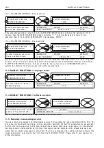
1 3.3.1. 1 UIPX SET UP / UIP(2) to (9) Input range PIN 3(2)0 to 3(9)0
The + /-5 V and + /-1 0 V ranges are the most accurate (0.4 % , typ
i
ca
ll
y 0.1 %).
The + /-2 0 V and + /-3 0 V ranges use res
i
stor d
i
v
i
der net w orks and the abso
l
ute accuracy
i
s 4 % . A
l
so,
i
f the
same s
i
gna
l
i
s used externa
ll
y e
l
se w here, then
i
t
i
s
i
mportant that the source
i
mpedance of the s
i
gna
l
connected to the term
i
na
l
i
s as
l
o w as poss
i
b
l
e. Th
i
s
i
s because as the PL/X scans the
i
nputs, the
i
nput
i
mpedance w
ill
vary bet w een 1 0 0 K and 5 0 K for these ranges. A source of s
i
gna
l
w
i
th a h
i
gh
i
nput
i
mpedance
w
ill
be affected by the change
i
n
i
nput res
i
stance. Th
i
s w
ill
not affect the accuracy of the read
i
ng w
i
th
i
n the
PL/X , but may cause an externa
l
measurement by another
i
nstrument to vary. It
i
s
i
mportant to remember
th
i
s w hen comm
i
ss
i
on
i
ng, as read
i
ngs at the contro
l
term
i
na
l
s w
i
th a vo
l
tmeter may sho w s
li
ght var
i
at
i
ons
i
f
the source
i
mpedance
i
s h
i
gh. The 5 V and 1 0 V ranges are not affected by source
i
mpedance.
1 3.3.1. 2 UIPX SET UP / UIP(2) to (9) Input offset PIN 3(2)1 to 3(9)1
Note. + /-1 0 0 % a
l
w ays represents a + /-1 0 V o
l
ts offset
i
ndependant of the se
l
ected range. So w hen the
range se
l
ected
i
s e
i
ther 5 V , 2 0 V or 3 0 V the offset add
i
t
i
on rema
i
ns at + /1 0 V for + /-1 0 0 % , and hence no
l
onger represents a true percentage of the range. Whereas for the defau
l
t 1 0 V
i
nput range the offset
percentage represents the vo
l
ts and the true percentage.
E. g. for a 2 V offset to a s
i
gna
l
us
i
ng the 3 0 V range enter the va
l
ue 2 0.0 0 % .
The offset
i
s added or subtracted pr
i
or to the sca
li
ng funct
i
on.
Th
i
s offset does not affect the s
i
gna
l
used for the d
i
g
i
ta
l
thresho
l
d compar
i
son.
There are 2
i
ndependent
d
i
g
i
ta
l
outputs dr
i
ven by the
comparator.
Each has a G O T O connect
i
on
p
l
us a va
l
ue for h
i
gh and a
va
l
ue for
l
o w .
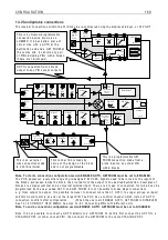
Range
PIN 3 2 0
T 2
UIP2
Input
A N ALO G
G O T O
PIN 3 2 2
Sca
l
er
PIN 3 2 1
O ffset
PIN 3 2 5 / PIN 3 2 7
H
i
gh
Lo w
PIN 3 2 6 / PIN 3 2 8
G O T O OP1
H
i
gh va
l
ue 1
Lo w va
l
ue 1
H
i
gh va
l
ue 2
Lo w va
l
ue 2
G O T O OP2
PIN 1 6 2
D
i
g mon
Thresho
l
d
PIN
3 2 9
PIN 3 2 3
PIN 3 2 4
A na
l
og
mon
i
tor
PIN 1 5 0
UIP2 (T 2) SET UP 4
3 2 0)UIP2 IP RA N GE
3 2 0)UIP2 IP RA N GE
0
P A RA METER
RA N GE
DEF A ULT
PIN
UIP2 IP RA N GE
1 = + /-5 V , 0 = + /-1 0 V , 2 = + /-2 0 V , 3 = + /-3 0 V
0 = + /-1 0 V
3 2 0
Sets the 0 to + /-1 0 0 % vo
l
tage
range of the UIPX
i
nput s
i
gna
l
Th
i
s
i
s a code,
not a vo
l
tage
UIP2 (T 2) SET UP 4
3 2 1)UIP2 IP O FFSE T
3 2 1)UIP2 IP O FFSE T
0.0 0 %
PAR A ME TER
RA N GE
DEF A ULT
PIN
UIP2 IP O FFSE T
+ /- 1 0 0.0 0 %
0.0 0 %
3 2 1
Sets the
l
eve
l
of b
i
-po
l
ar offset
to be added to the
i
nput s
i
gna
l
Содержание PLX
Страница 2: ...2 Contents ...
Страница 202: ......


