C O NFIG URA TIO N
1 7 5
1 3.3.1. 2.1
4-2 0 m A
l
oop
i
nput SET UP
W hen us
i
ng 4-2 0m A
l
oop s
i
gna
l
s a
ll
that
i
s requ
i
red
i
s to f
i
t an externa
l
burden res
i
stor of 2 2 0 Ohms bet w een the
i
nput and 0 V . The resu
l
t
i
ng
vo
l
tage s
i
gna
l
generated by pass
i
ng the s
i
gna
l
current through the burden
w
ill
be + 0.8 8 V for 4 m A (represents 0 %) and 4.4 V for 2 0m A (represents
1 0 0 %). Us
i
ng the appropr
i
ate UIPX SET UP b
l
ock, se
l
ect the fo
ll
o w
i
ng :-
5 V range
(Max vo
l
tage generated by
l
oop across burden = 4.4 V)
-8.8 % offset (4m A g
i
ves 0.8 8 V). (offset
i
s a
l
w ays + /-1 0 0 % = + /-1 0 V)
1.4 2 0 sca
li
ng factor ((4.4 – 0.8 8) X 1. 4 2 0 = 5 V
i
.e 1 0 0 %)
For burden res
i
stors of other va
l
ues, the range, offset and sca
l
e w
ill
d
i
ffer
accord
i
ng
l
y.
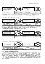
1 3.3.1. 3 UIPX SET UP / UIP(2) to (9) L
i
near sca
li
ng rat
i
o PIN 3(2)2 to 3(9)2
Note. Th
i
s does not affect the s
i
gna
l
used for the d
i
g
i
ta
l
thresho
l
d compar
i
son. Th
i
s sca
li
ng factor may be
used to
i
ntroduce an
i
nvers
i
on by se
l
ect
i
ng a negat
i
ve number. A sca
li
ng factor of 1.0 0 0 0
i
s equ
i
va
l
ent to
1 0 0. 0 0 % . In th
i
s case the fu
ll
range of the
i
nput as se
l
ected
i
n the range se
l
ect
i
on w
i
ndo w w
ill
be equ
i
va
l
ent
to a 1 0 0.0 0 % s
i
gna
l
. E. g. W
i
th the 3 0 V range se
l
ected and a sca
li
ng factor of 1.0 0 0 0, then a s
i
gna
l
of 3 0 V
w ou
l
d represent a demand of 1 0 0.0 0 % speed.
1 3.3.1. 4 UIPX SET UP / UIP(2) to (9) Max
i
mum c
l
amp
l
eve
l
PIN 3(2)3 to 3(9)3
1 3.3.1. 5 UIPX SET UP / UIP(2) to (9) M
i
n
i
mum c
l
amp
l
eve
l
PIN 3(2)4 to 3(9)4
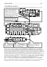
UIP
0 V
2
2
0
R
UIP2 (T 2) SET UP 4
3 2 2)UIP2 C AL RA TIO
3 2 2)UIP2 C AL RA TIO
1.0 0 0 0
PAR A ME TER
RA N GE
DEF A ULT
PIN
UIP2 C AL R A TIO + /- 3.0 0 0 0
1.0 0 0 0
3 2 2
A
ll
o w s
li
near sca
li
ng of the
s
i
gna
l
on the UIPX
i
nput.
UIP2 (T 2) SET UP 4
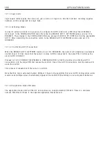
3 2 3)UIP2 M A X CL A MP
3 2 3)UIP2 M A X CL A MP
+ 1 0 0.0 0 %
PAR A ME TER
RA N GE
DEF A ULT
PIN
UIP2 M A X CL A MP + /- 3 0 0.0 0 %
+ 1 0 0.0 0 %
3 2 3
Sets an upper c
l
amp
l
eve
l
for
the sca
l
ed
li
near
i
nput s
i
gna
l
.
UIP2 (T 2) SET UP 4
3 2 4)UIP2 MIN CL A MP
3 2 4)UIP2 MIN CL A MP
-1 0 0.0 0 %
PAR A ME TER
RA N GE
DEF A ULT
PIN
UIP2 MIN CL A MP
+ /- 3 0 0.0 0 %
-1 0 0.0 0 %
3 2 4
Sets a
l
o w er c
l
amp
l
eve
l
for the
sca
l
ed
li
near
i
nput s
i
gna
l
.
Содержание PLX
Страница 2: ...2 Contents ...
Страница 202: ......


