2 6
Introduct
i
on and Techn
i
ca
l
Data
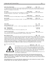
3.4.2.1 Encoder
i
nputs
Note. DIP3 (T 1 6, B tra
i
n or s
i
gn) and DIP4 (T 1 7, A tra
i
n) are des
i
gned to accept b
i
-d
i
rect
i
ona
l
encoder pu
l
se
tra
i
ns. DIP2 (T 1 5)
i
s des
i
gned to accept a M ARKER for sp
i
nd
l
e or
i
entat
i
on. The encoder outputs must be ab
l
e
to prov
i
de a
l
og
i
c
l
o w be
l
o w 2 V , a
l
og
i
c h
i
gh above 4 V , may range up to 5 0 V max and up to 1 0 0 KHz. These
2
i
nputs are s
i
ng
l
e ended and non-
i
so
l
ated. For other types of encoder output, the user must prov
i
de some
externa
l
cond
i
t
i
on
i
ng c
i
rcu
i
try. The output format may be pu
l
se on
l
y for s
i
ng
l
e d
i
rect
i
on, pu
l
se w
i
th s
i
gn, or
phase quadrature. See 6.1.1 0 C ALIBRA TIO N / EN C O DER S C ALIN G.
Not
e
. Th
e
U
I
P
s off
e
r
mu
c
h h
i
gh
e
r
no
i
s
e
i
mmun
i
ty fo
r
24V
l
og
i
c
s
i
gn
a
l
s.
3.4.2.2 D
i
g
i
ta
l
outputs
W hen the d
i
g
i
ta
l
outputs are shorted the 2 4 V output w
ill
cont
i
nue to operate w
i
th a current capab
ili
ty of
5 0m A . Th
i
s
i
s so that the C ST OP
li
ne does not go
l
o w and shut do w n the dr
i
ve. If
i
t
i
s
i
mportant that the
dr
i
ve cont
i
nues runn
i
ng w
i
th a shorted d
i
g
i
ta
l
output then a d
i
g
i
ta
l
output set permanent
l
y h
i
gh may be used
as an aux
ili
ary 2 4 V po w er output for other tasks, a
ll
o w
i
ng the ma
i
n 2 4 V output to be devoted ent
i
re
l
y to the
C ST OP funct
i
on.
The current capab
ili
ty of the d
i
g
i
ta
l
outputs
i
s a
l
so an
i
mportant
i
ssue. T yp
i
ca
ll
y 5 0 m A
i
s a suff
i
c
i
ent
spec
i
f
i
cat
i
on. Ho w ever occas
i
ona
ll
y h
i
gher output current
i
s requ
i
red. The PL/X ser
i
es addresses th
i
s by
a
ll
o w
i
ng a tota
l
current
li
m
i
t to be made ava
il
ab
l
e to a
ll
the d
i
g
i
ta
l
outputs, a
ll
o w
i
ng the user to exp
l
o
i
t
i
t as
des
i
red. For a
ll
7 outputs together there
i
s a max
i
mum a
ll
o w ab
l
e
li
m
i
t of 3 5 0 m A . A ny one output
i
s a
ll
o w ed
to output up to 3 5 0m A . A ny spare capac
i
ty w
i
th
i
n th
i
s
li
m
i
t
i
s a
l
so ava
il
ab
l
e to the 2 4 V output, w h
i
ch a
l
so
has
i
ts o w n 5 0m A capab
ili
ty, g
i
v
i
ng a max
i
mum tota
l
to the + 2 4 V output of 4 0 0 m A
i
f no d
i
g
i
ta
l
output
i
s
be
i
ng used.
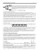
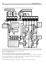
Th
i
s sho w s the output conf
i
gurat
i
on for each d
i
g
i
ta
l
output D OP1 to D OP3 and DIO 1 to DIO 4
The d
i
g
i
ta
l
outputs are a
l
so des
i
gned to be OR,d together, or w
i
th outputs from other dr
i
ves
i
f des
i
red. Th
i
s
i
s
somet
i
mes usefu
l
i
f an externa
l
event must w a
i
t for severa
l
outputs to go
l
o w . Each output
i
s f
i
tted w
i
th a
f
l
y w hee
l
d
i
ode to a
ll
o w the safe dr
i
v
i
ng of
i
nduct
i
ve
l
oads, and because of the current
li
m
i
t
i
ng
i
t
i
s poss
i
b
l
e to
dr
i
ve
l
amps that may have a
l
o w co
l
d res
i
stance.
3.4.3 A na
l
ogue
i
nputs
UIP2 to UIP9
The ana
l
ogue
i
nputs are requ
i
red to accurate
l
y measure + /-1 0 V s
i
gna
l
s. The reso
l
ut
i
on (m
i
n
i
mum
recogn
i
sab
l
e steps) must be as sma
ll
as poss
i
b
l
e and the convers
i
on to a number must be as fast as poss
i
b
l
e
to g
i
ve good response t
i
mes. The PL/X ser
i
es not on
l
y possesses 8 ana
l
ogue
i
nputs, but a
l
so measures a
ll
of
these w
i
th up to 5m V p
l
us s
i
gn reso
l
ut
i
on and w
i
th exce
ll
ent response t
i
me. In add
i
t
i
on
i
t
i
s poss
i
b
l
e to
programme the vo
l
tage range of each
i
nput to + /- 5, 1 0, 2 0 or 3 0 V . Th
i
s a
ll
o w s s
i
gna
l
s other than 1 0 V fu
ll
sca
l
e to be used, and enab
l
es the
i
nput to be used as a soph
i
st
i
cated d
i
g
i
ta
l
i
nput. Th
i
s can be ach
i
eved by
programm
i
ng the
i
nput to the 3 0 V range and sett
i
ng the programmab
l
e thresho
l
d detector at 1 5 V to
recogn
i
se a 0 or 1. A
ll
the ana
l
ogue
i
nput vo
l
tages can be mon
i
tored us
i
ng the bu
il
t
i
n menus, w h
i
ch w
ill
d
i
sp
l
ay
i
n the se
l
ected ranges of + /- 5.1 2 0 V , + /-1 0.2 4 0 V , + /-2 0.4 8 0 V and + /-3 0.7 2 0 V o
l
ts.
See 6.7.7.7 SPEED PI A D APTIO N / Us
nputs. The defau
l
t g
i
ves
l
o w ga
i
n for sma
ll
i
nputs.
Not
e
. Wh
e
n us
e
d
a
s d
i
g
i
t
a
l
i
nputs th
e
U
I
P
s p
r
ov
i
d
e
e
x
ce
ll
e
nt no
i
s
e
i
mmun
i
ty
a
nd s
e
tt
a
b
l
e
th
r
e
sho
l
d.
Output term
i
na
l
F
l
y w hee
l
d
i
ode
Interna
l
current
li
m
i
ted (35 0m A) + 2 4 V
0 V term
i
na
l
Externa
l
l
oad.
E.g. re
l
ay co
il
A
ll
d
i
g
i
ta
l
outputs
share th
i
s ra
il
Содержание PLX
Страница 2: ...2 Contents ...
Страница 202: ......


