9 2
C H A N GE PARA METERS
M O T ORISED PO T RA MPS 3
5 2)UP TIME 4
C H A N GE PAR A METERS 2
SPEED C O N TROL 3
R
SPEED C O N TROL 3
SPEED PI A D APTIO N 4
SPEED C O N TROL 3
6 9)M A X PO S SPEED REF
SPEED C O N TROL 3
7 3)SPEED IN T RESET
SPEED C O N TROL 3
7 0)M A X NE G SPEED REF
SPEED C O N TROL 3
7 1)SPEED PROP G AIN
SPEED C O N TROL 3
7 2)SPEED IN T T. C.
R
R
R
R
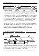
6.6.7 SPEED REF SU M MER / Speed/Current Reference 3 rat
i
o PIN 6 7
The
i
nterna
l
connect
i
on from UIP3 to 6 4)SPEED REF 3 M O N
i
s permanent. Ho w ever 6 4)SPEED REF 3 M O N
may be d
i
sconnected from the SPEED REF SU M MER by sett
i
ng 6 7)SPD/C UR RF 3 RA TIO to 0.0 0 0 0.
6.7 CHANGE
P
A
R
AMETE
R
S / S
P
EED CONT
R
O
L
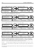
PIN number range 6 9 to 7 9
Th
i
s menu a
ll
o w s parameter ad
j
ustment for the
speed
l
oop error amp
li
f
i
er. It cons
i
sts of th
i
s
li
st
and a sub menu ca
ll
ed SPEED PI A D APTIO N. Th
i
s
menu refers to the b
l
ock d
i
agram be
l
o w , start
i
ng
after the second summ
i
ng
j
unct
i
on. The summed
va
l
ue of a
ll
the references
i
s sub
j
ect to a max
i
mum
+ ve and -ve c
l
amp. It then enters the stop mode
ramp b
l
ock. Th
i
s super
i
mposes a ramp to zero at a
programmed rate on the preva
ili
ng
i
nput s
i
gna
l
dur
i
ng a stop command. W hen a run command
i
s
rece
i
ved the output
i
mmed
i
ate
l
y assumes the
l
eve
l
then preva
ili
ng at the
i
nput. Th
i
s
l
eve
l
w
ill
norma
ll
y
a
l
so be zero prov
i
d
i
ng the run mode ramp b
l
ock
has a
l
so been reset. The s
i
gna
l
i
s then compared
w
i
th the speed feedback and processed by the
speed
l
oop error amp
li
f
i
er.
The bas
i
c PI ga
i
n and t
i
me constants are ad
j
ustab
l
e
i
n th
i
s
li
st, and w
i
th further soph
i
st
i
cat
i
on
i
n the sub
li
st
SPEED PI A D APTIO N. A fter be
i
ng output from the error amp
li
f
i
er the s
i
gna
l
no w represents current reference.
Th
i
s current reference s
i
gna
l
i
s then se
l
ected for output by the speed bypass change over s w
i
tch. If the
speed bypass mode
i
s enab
l
ed then
i
nput reference 3
i
s se
l
ected.
Note. The defau
l
t va
l
ues
i
n th
i
s menu have been chosen to su
i
t tacho or encoder feedback. A V F feedback
usua
ll
y conta
i
ns more r
i
pp
l
e than tacho or encoder feedback, hence
i
t
i
s adv
i
sab
l
e to reduce the SPEED
C O N TROL
l
oop ga
i
ns w henever A V F or EN C O DER + ARM V OLTS feedback
i
s se
l
ected. See 6.7.4 SPEED
In the case of A V F,
i
t
i
s suggested that the va
l
ues for the fo
ll
o w
i
ng parameters are changed as fo
ll
o w s.
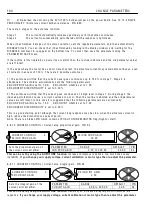
6.7.4 SPEED C O N TROL / Speed proport
n PIN 7 1 set to 7.0 0.
6.7.7.6 SPEED PI A D APTIO N / Speed
e PIN 7 9 set to DIS A BLED.
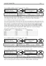
These are suggested start
i
ng po
i
nts for smooth respons
i
ve contro
l
, ho w ever
i
t may be poss
i
b
l
e to make
i
mprovements w
i
th further exper
i
mentat
i
on.
SPEED REF SU M MER 3
6 7)SPD/ C UR RF 3 R A TIO
6 7)SPD/ C UR RF 3 R A TIO
1.0 0 0 0
PAR A ME TER
RA N GE
DEF A ULT
PIN
SPD/C UR RF 3 RA TIO
+ /-3.0 0 0 0
1.0 0 0 0
6 7
Sets a sca
li
ng factor for
Speed/current reference 3.
R
R
Содержание PLX
Страница 2: ...2 Contents ...
Страница 202: ......


