1 8 0
C O NFIG URA TIO N
C O NFIGUR A TIO N 2
DIGIT AL INPU TS 3
DIGIT AL INPU TS 3
RUN INPU T SET UP 4
DIGIT AL INPU TS 3
DIP1 (T 1 4) SET UP 4
DIGIT AL INPU TS 3
DIP2 (T 1 5) SET UP 4
DIGIT AL INPU TS 3
DIP3 (T 1 6) SET UP 4
DIGIT AL INPU TS 3
DIP4 (T 1 7) SET UP 4
PIN 3 1 0
PIN 3 1 1
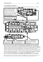
T 1 4
DIP mon
i
tor
PIN
1 6 3
DIPX
H
i
gh va
l
ue
Lo w va
l
ue
G O T O
Encoder b
l
ocks
1 3.4.3 A N ALO G O U TPU TS / Scope output se
l
ect PIN 2 6 0
The s
i
gna
l
output
i
s automat
i
ca
ll
y s w
i
tched to the d
i
sp
l
ayed parameter, and prov
i
des a
li
near s
i
gned s
i
gna
l
.
The output sca
l
e may be changed by us
i
ng 2 5 7)A OP3 DIVIDER (defau
l
t 1 0 0 % g
i
ves 1 0 V). Th
i
s a
ll
o w s very
rap
i
d se
l
ect
i
on of the s
i
gna
l
source for d
i
sp
l
ay on an osc
ill
oscope.
Note. A ny
i
nterna
l
GET FRO M connect
i
on made to A OP3
i
s
l
eft
i
ntact but
i
gnored by 2 6 0)S C OPE OP SELE C T
funct
i
on.
13.5 CONF
I
GU
R
AT
I
ON / D
I
G
I
TA
L
I
N
P
UTS
P
i
ns 3 1 0 to 3 1 9
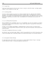
There are 4 d
i
g
i
ta
l
l
og
i
c
i
nputs DIP1/2/3/4 on
term
i
na
l
s T 1 4/1 5/1 6/1 7, p
l
us the RUN
i
nput on
T 3 1. The DIP
i
nputs may a
l
so be used for
i
ncrementa
l
encoder or reg
i
ster mark
i
nputs. In
th
i
s case the
l
og
i
c funct
i
ons w
ill
cont
i
nue to
operate as descr
i
bed here.
The LO and HI va
l
ues can be entered us
i
ng the d
i
sp
l
ay and keys, or may be connected to other output PINs
us
i
ng JU MPERS. Th
i
s turns the funct
i
on
i
nto a change-over s w
i
tch for dynam
i
c va
l
ues. For
l
og
i
c on
l
y usage a
va
l
ue of 0.0 0 %
i
s read as a
l
o w . A ny non zero + /- va
l
ue
i
s read as a h
i
gh. Log
i
c
i
nvers
i
on
i
s accomp
li
shed
by enter
i
ng 0.0 0 %
i
n the va
l
ue for HI w
i
ndo w and 0.0 1 %
i
n the va
l
ue for LO w
i
ndo w .
1 3.5.1 Us
i
ng DIP
i
nputs for encoder s
i
gna
l
s.
Log
i
c thresho
l
ds.
0 < 2 V , 1 > 4 V
Note. W hen us
i
ng encoders w
i
th quadrature outputs
i
t
i
s very
i
mportant that the phase re
l
at
i
onsh
i
p of the 2
pu
l
se tra
i
ns rema
i
ns as c
l
ose to 9 0 degrees as poss
i
b
l
e. If the encoder
i
s not mounted and centered
accurate
l
y on the shaft,
i
t can cause ske w
i
ng of the
i
nterna
l
opt
i
cs as the shaft rotates through 3 6 0 degrees.
Th
i
s produces a severe degradat
i
on of the phase re
l
at
i
onsh
i
p on a cyc
li
ca
l
bas
i
s. If the encoder appears to
gyrate as the shaft rotates you must rect
i
fy the prob
l
em before try
i
ng to proceed w
i
th comm
i
ss
i
on
i
ng. The
best w ay of check
i
ng the output
i
s to use a h
i
gh qua
li
ty osc
ill
oscope and observe both pu
l
se tra
i
ns for good
phase ho
l
d
i
ng and no
i
nterference. Do th
i
s w
i
th the dr
i
ve rotat
i
ng to + /- 1 0 0 % speed us
i
ng A V F as the
feedback source.
Not
e
.
I
f
a
l
og
i
c
i
nput w
i
th h
i
gh no
i
s
e
i
mmun
i
ty
i
s
r
e
qu
ir
e
d
i
t
i
s
r
ec
omm
e
nd
e
d to us
e
a
U
I
P
.
See 6.1.1 0 C ALIBR A TIO N / EN C O DER S C ALIN G for more
i
nformat
i
on about encoder feedback.
A N ALO G O U TPU TS 3
2 6 0)S C OPE OP SELE C T
2 6 0)S C OPE OP SELE C T
DIS A BLED
PAR A ME TER
RA N GE
PIN
S C OPE OP SELE C T
EN A BLED or DIS A BLED
2 6 0
Enab
l
es A OP3 to output the va
l
ue of the
parameter
i
n any d
i
sp
l
ay w
i
ndo w .
Содержание PLX
Страница 2: ...2 Contents ...
Страница 202: ......


