3 4
Bas
i
c app
li
cat
i
on
4.1 B
a
s
i
c
sp
ee
d o
r
to
r
qu
e
c
ont
r
o
l
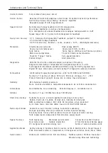
Th
i
s sect
i
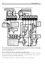
on sho w s the essent
i
a
l
requ
i
rements for a very bas
i
c speed or torque contro
l
app
li
cat
i
on.
Note that the arrangement of the contactor sho w n here a
ll
o w s cont
i
nuous phase sens
i
ng on EL1/2/3.
VE
R
Y
I
M
P
O
R
TANT
see 4.2 Ma
Not
e
. B1, B2 F
a
n supp
l
y
i
s 110V AC 50VA fo
r
PL
/X185-265
a
nd 240V AC 100VA fo
r
PL
/X 275-980.
1
0
V
1 3
0
V
2 3 4 5 6 7 8 9 1 0 1 1 1 2
U
IP
2
U
IP
3
U
IP
4
U
IP
5
U
IP
6
U
IP
7
U
IP
8
A
O
P
1
A
O
P
2
A
O
P
3
0
V
D
IP
1
D
IP
2
D
IP
3
D
IP
4
1 4 1 5 1 6 1 7 1 8 1 9 2 0 2 1 2 2 2 3 2 4
D
IO
1
D
IO
2
D
IO
3
D
IO
4
D
O
P
1
D
O
P
2
D
O
P
3
2 5 2 6 2 7 2 8 2 9 3 0 3 1 3 2 3 3 3 4 3 5 3 6
T
A
C
H
+
1
0
-1
0
IA
R
M
T
H
M
R
U
N
JO
G
S
T
A
R
T
C
ST
O
P
+
2
4
V
0
V
4 1 4 2 4 3 4 4 4 5 4 6
5 1 5 2 5 3
R
A
+
N
C
R
A
-
C
O
N
1
EA
R
TH
N
L
N
C
C
O
N
2
A +
A-
L1
L2
L3
EL
1
EL
2
EL
3
F-
F
+
TERMIN A LS 1 -1 2 F UN C TIO N
T ERMIN A LS 1 3 -2 4 F U N C TIO N
1 1 0 V
A C IP
F A N
B1 B2
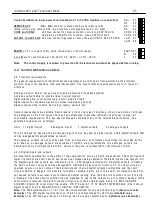
Term
i
na
l
s sho w n on the top edge are
l
ocated on the
l
o w er
l
eve
l
po w er board. (B1/B2 on top edge of 1 8 5/2 2 5/2 6 5 mode
l
s)
Symbo
li
c connect
i
on b
l
ock.
Term
i
na
l
s 1 - 36 are
l
ocated on the
bottom edge of the upper contro
l
board arranged as 3 b
l
ocks of 1 2.
Term
i
na
l
s 2 -1 2, 1 4 - 24, and 3 1
are programmab
l
e.
The
i
r defau
l
t funct
i
on
i
s sho w n here.
Sp
ee
d
re
f/
Cu
rr
en
t r
ef
R
am
p
ed
S
p
ee
d
S
et
p
o
i
n
t
Lo
w
er
C
ur
re
nt
C
l
am
p
M
a
i
n/
U
pp
er
C
ur
re
nt
C
l
am
p
M
o
to
r
i
se
d
P
o
t
P
re
se
t
M
o
to
r
i
se
d
P
o
t
In
cr
ea
se
M
o
to
r
i
se
d
P
o
t
d
ec
re
as
e
S
p
ee
d
F
ee
d
b
ac
k
0
V
T
er
m
i
n
a
l
To
ta
l
S
p
ee
d
R
e
fe
re
n
ce
To
ta
l
C
ur
re
nt
D
em
an
d
S
p
ee
d
R
ef
er
en
ce
0
V
T
er
m
i
n
a
l
Z
er
o
r
ef
er
en
ce
i
n
te
r
l
o
ck
Jo
g
S
p
ee
d
S
e
l
ec
t
R
am
p
H
o
l
d
C
ur
re
n
t
C
l
am
p
S
e
l
ec
t
Sp
ar
e
i
np
ut
Sp
ar
e
i
np
ut
Fe
ed
ba
ck
e
nc
od
er
Fe
ed
ba
ck
e
nc
od
er
Z
er
o
S
p
ee
d
Ra
m
p
i
ng
f
l
ag
D
r
i
ve
H
ea
l
th
y
contactor
co
il
supp
l
y
1 1 0 V A C
3 phase
motor
b
l
o w er
c
i
rcu
i
t
breaker
ma
i
n
sem
i
-conductor
fuses
ma
i
n
contactor
ma
i
n
contactor
co
il
Iso
l
ator
armature
f
i
e
l
d
li
ne
reactor
aux
ili
ary
sem
i
-conductor
fuses
L3
L2
L1
1 0K
speed pot
c w
ac w
emergency
stop re
l
ay
start
j
og
run
T
+
therm
i
stor
U
IP
9
A C Contro
l
Supp
l
y Inputs
(110 -2 40 V)
Protect
i
ve
c
l
ean earth.
Contro
l
supp
l
y
d
i
rty earth
4 7 48
L
A
T
1
L
A
T
2
Substant
i
a
l
ch ass
i
s
earth
Use D C sem
i
conductor
fuse for
regen
app
li
cat
i
ons
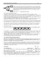
W ARNIN G. Do not
a
ll
o w co
il
supp
l
y to be
externa
ll
y
i
nterrupted.
Re
t
r
o- f
i
t
r
e
l
a
y
l
og
i
c
i
s
oft
e
n th
e
m
a
i
n
c
u
l
p
ri
t.
W ARNIN G
The phase order
of EL1/2/3 must
be the same as
L1/2/3
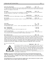
For Torque contro
l
enter Torque ref
i
nto T 6. (0 - 1 0 V).
For speed contro
l
li
nk T 6 to + 1 0 V
on T 2 7.
A C 1 rated
Содержание PLX
Страница 2: ...2 Contents ...
Страница 202: ......


