C H A N GE PARA METERS
6 7
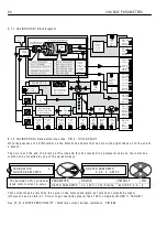
6.1.1 0. 2 EN C O DER S C ALIN G / Encoder
li
nes PIN 1 1
The number of
li
nes on the encoder datap
l
ate shou
l
d be entered. A
l
ternat
i
ve
l
y enter the number of cyc
l
es of
h
i
gh/
l
o w for one pu
l
se tra
i
n dur
i
ng one revo
l
ut
i
on. E. G. for a toothed gear w hee
l
w
i
th 6 0 teeth and a
magnet
i
c p
i
ck up, enter the number 6 0. Note that there
i
s an upper frequency
li
m
i
t of 1 0 0 kHz.
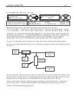
6.1.1 0. 3 EN C O DER S C ALIN G / Motor / encoder speed rat
i
o PIN 1 2
Note. The encoder
i
s somet
i
mes not f
i
xed to the motor shaft, and may rotate at an RPM that
i
s a non un
i
ty
rat
i
o of the motor RPM. Some systems have the encoder geared up to obta
i
n a h
i
gher feedback frequency.
M O T/EN C SPD R A TIO = Motor RPM / Encoder RPM
(true for a
ll
speeds)
W hen us
i
ng encoders
i
t
i
s adv
i
sab
l
e to
i
n
i
t
i
a
ll
y run the system
i
n A V F mode to ver
i
fy the
i
ntegr
i
ty of the
encoder feedback s
i
gna
l
s us
i
ng an osc
ill
oscope. Then after sett
i
ng the Q U A DRA T URE EN A BLE and EN C O DER
LINES parameters, run the system
i
n A V F feedback mode, and mon
i
tor 1 3 2)EN C O DER RPM
i
n the
DIA GN O S TIC S menu. Th
i
s w
ill
ver
i
fy the encoder operates as expected pr
i
or to us
i
ng
i
t as a feedback source.
Note. A n encoder may be
i
nput and used for other tasks
i
nstead of feedback.
On h
i
dden PIN 7 0 9)M O T OR RPM % ,
i
s the encoder feedback % , sca
l
ed to 1 0 0 % = 6)DESIRED M A X RPM.
It
i
s a
l
so sca
l
ed by 1 2)M O T/EN C SPD R A TIO w h
i
ch acts as a pure mu
l
t
i
p
l
y
i
ng factor.
Both 132
)
ENCODE
R
RP
M
a
nd
P
I
N 709
)
MOTO
R
RP
M %,
a
r
e
pu
r
e
l
y
e
n
c
od
e
r
s
i
gn
a
l
s, th
a
t wo
r
k
i
nd
e
p
e
nd
e
nt
l
y
of th
e
typ
e
of f
ee
db
ack
s
e
l
ec
t
e
d. Th
e
y both
r
ea
d z
e
r
o w
i
th no pu
l
s
e
s on th
e
e
n
c
od
e
r
i
nputs.
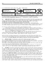
6.1.1 0. 4 EN C O DER S C ALIN G / Encoder s
i
gn PIN 1 3
Use th
i
s to
i
nvert the encoder feedback s
i
gn
i
f needed. Note,
i
n comb
i
ned feedback modes type 3 and 4,
w
i
th s
i
ng
l
e
li
ne encoders, the feedback s
i
gn
i
s automat
i
ca
ll
y taken from the A V F or tacho
i
f SPIN DLE
ORIEN T A TE
i
s not emp
l
oyed. (T 1 6 d
i
g
i
ta
l
i
nput
i
s made free for other uses).
EN C O DER S C ALIN G 4
1 1) EN C O DER LINES
1 1)EN C O DER LINES
1 0 0 0
PAR A ME TER
RA N GE
DEF A ULT PIN
EN C O DER LINES
1 to 6 0 0 0
1 0 0 0
1 1
Inputs the encoder reso
l
ut
i
on
i
n
pu
l
ses per rev .
R
R
EN C O DER S C ALIN G 4
1 2)M O T/EN C SPD RA TIO
1 2)M O T/EN C SPD RA TIO
1.0 0 0 0
PAR A ME TER
RA N GE
DEF A ULT PIN
M O T/EN C SPD R A TIO
0.0 0 0 0 to 3.0 0 0 0
1.0 0 0 0
1 2
Sets the motor revs as a rat
i
o
of the encoder revs.
R
R
EN C O DER S C ALIN G 4
1 3)EN C O DER SIG N
1 3)EN C O DER SIG N
N O N-IN V ERT
PAR A ME TER
RA N GE
DEF A ULT
PIN
EN C O DER SIGN
N O N-IN V ERT or IN V ERT
N O N-IN V ERT
1 3
Mod
i
f
i
es the encoder rotat
i
on
s
i
gn.
R
R
Содержание PLX
Страница 2: ...2 Contents ...
Страница 202: ......


