2 2
Introduct
i
on and Techn
i
ca
l
Data
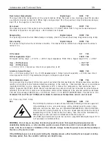
3.3 G
e
n
e
r
a
l
T
ec
hn
i
ca
l
D
a
t
a
Rat
i
ng tab
l
e
Max
i
mum cont
i
nuous shaft rat
i
ngs
Mode
l
PL 2 quadrant
PLX 4 quadrant
k W
at 4 6 0 V
HP
at 4 6 0 V
HP
at 5 0 0 V
1 0 0 %
Armature
Current
D C
A mps
1 0 0 %
F
i
e
l
d
A mps
D
i
mens
i
ons mm
(force vented = fv)
W x H x D
*PL and PLX
5
5
6.6
7.5
1 2
8
2 1 6 x 2 8 9 x 1 7 4
*PL and PLX
1 0
1 0
1 3.3
1 5
2 4
8
2 1 6 x 2 8 9 x 1 7 4
*PL and PLX
1 5
1 5
2 0
2 0
3 6
8
2 1 6 x 2 8 9 x 1 7 4
*PL and PLX
2 0
2 0
2 6.6
3 0
5 1
8
2 1 6 x 2 8 9 x 1 7 4
*PL and PLX
3 0
3 0
4 0
4 0
7 2
8
2 1 6 x 2 8 9 x 1 7 4 fv
*PL and PLX
4 0
4 0
5 3.3
6 0
9 9
8
2 1 6 x 2 8 9 x 1 7 4 fv
*PL and PLX
5 0
5 0
6 6.6
7 5
1 2 3
8
2 1 6 x 2 8 9 x 1 7 4 fv
PL and PLX
6 5
6 5
9 0
1 0 0
1 5 5
1 6
2 1 6 x 3 7 8 x 2 1 8 fv
PL and PLX
8 5
8 5
1 1 5
1 2 5
2 0 5
1 6
2 1 6 x 3 7 8 x 2 1 8 fv
PL and PLX
1 1 5
1 1 5
1 5 5
1 6 0
2 7 0
1 6
2 1 6 x 3 7 8 x 2 1 8 fv
*PL and PLX
1 4 5
1 4 5
1 9 0
2 0 0
3 3 0
1 6
2 1 6 x 3 7 8 x 2 1 8 fv
PL and PLX
1 8 5
1 8 5
2 5 0
2 7 0
4 3 0
3 2 or 5 0
2 1 6 x 3 7 8 x 3 1 4 fv
*PL and PLX
2 2 5
2 2 5
3 0 0
3 3 0
5 3 0
3 2 or 5 0
2 1 6 x 3 7 8 x 3 1 4 fv
PL on
l
y
2 6 5
2 6 5
3 5 0
4 0 0
6 3 0
3 2 or 5 0
2 1 6 x 3 7 8 x 3 1 4 fv
P
l
ea
s
e
a
l
so
r
e
f
e
r
to
Pa
r
t 3
PL
/X 275-980 fo
r
e
xt
r
a
d
e
t
a
il
s of f
r
a
m
e
4
a
nd 5 h
i
gh pow
e
r
d
ri
v
e
s.
3.3.1 Regenerat
i
ve stopp
i
ng w
i
th PL mode
l
s
* Starred mode
l
s: (*PL) 2 Q uadrant mode
l
s have e
l
ectron
i
c regenerat
i
ve stopp
i
ng.
See 6.5.2 ST OP M O DE R A MP / Stop ramp t
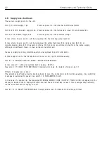
3.3.2 Supp
l
y vo
l
tages requ
i
red for a
ll
mode
l
s
The supp
li
es prov
i
ded must be su
i
tab
l
e for the motor emp
l
oyed
M
a
i
n 3 ph
a
s
e
50 - 6OHz
A ny supp
l
y from 1 2 to 4 8 0 V A C + /- 1 0 %
fo
r
a
r
m
a
tu
r
e
pow
e
r
.
Aux
ili
a
r
y 3 ph
a
s
e
50 - 6OHz
A ny supp
l
y from 1 0 0 to 4 8 0 V A C + /- 1 0 %
fo
r
f
i
e
l
d pow
e
r
.
Cont
r
o
l
1 ph
a
s
e
50 - 60Hz
A ny supp
l
y from 1 1 0 to 2 4 0 V A C + /- 1 0 % 5 0 V A .
Th
i
s
i
s
r
e
qu
ir
e
d to pow
e
r
th
e
PL
/X
e
l
ec
t
r
on
i
c
c
ir
c
u
i
ts.
PL
/X 185/225/265
mode
l
s a
l
so need a 5 0 V A 1 1 O V 5 0/6 O Hz
ac
f
a
n supp
l
y
PL
/X 650-980 f
r
a
m
e
4
a
nd 5 h
i
gh pow
e
r
d
ri
v
e
s
a
r
e
a
v
a
il
a
b
l
e
a
s HV v
e
r
s
i
ons fo
r
supp
li
e
s up to 690V AC.
OUT
P
UT VO
L
TAGE
R
ANGE
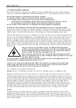
Armature
PLX and *PL 0 to + 1.2 t
i
mes A C supp
l
y.
PL 0 to + /- 1.3 t
i
mes A C supp
l
y.
Note. 1.1 t
i
mes A C supp
l
y
i
s recommended
i
f supp
l
y var
i
at
i
ons exceed – 6 % .
F
i
e
l
d
0 to 0.9 t
i
mes A C supp
l
y on aux
ili
ary term
i
na
l
s. (EL1, EL2, EL3)
OUT
P
UT CU
RR
ENT
R
ANGE
Armature
0 to 1 0 0 % cont
i
nuous.
1 5 0 % for 2 5 seconds
+ /- for PLX
F
i
e
l
d
programmab
l
e m
i
n
i
mum to 1 0 0 % cont
i
nuous w
i
th fa
il
a
l
arm.
Note. There
i
s a factory opt
i
on to a
ll
o w h
i
gh
i
nductance
l
oads to be dr
i
ven by the armature output.
Note. The 3 phase F
i
e
l
d and
Armature supp
li
es are
i
nput
through separate term
i
na
l
s and
may be at d
i
fferent
l
eve
l
s
i
f
des
i
red. See 1 4.9.1 W
i
r
i
ng d
i
agram
for A C supp
l
y to L1/2/3 d
i
fferent
to EL1/2/3. (E.g. Lo w vo
l
tage f
i
e
l
d)
Th
e
y must how
e
v
e
r
, b
e
i
n ph
a
s
e
Содержание PLX
Страница 2: ...2 Contents ...
Страница 202: ......


