5. Front Panel Menu orientation
5.11 System menu > Diagnostics
General
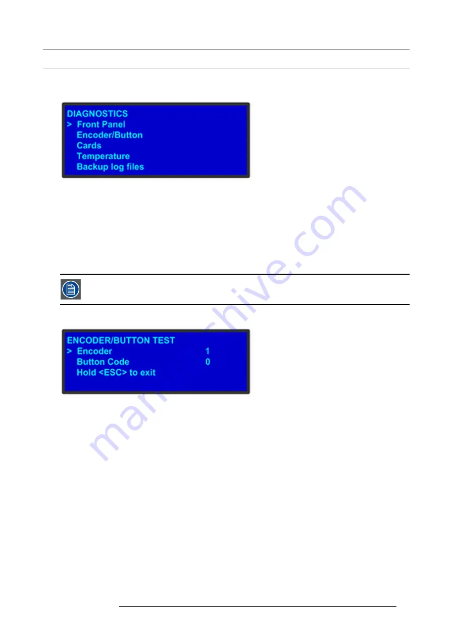
The following illustration shows the
Diagnostics
submenu, which you access from the
System
menu.
Image 5-15
The Diagnostics options allow a user to check if the E2 is functioning normally. Front panel and card operations can be checked.
Various system temperatures can be monitored and backup log
fi
les can be saved for customer service troubleshooting.
Front Panel
When
Front Panel
is selected to be tested, the VFD display will initially be blanked. Then the 24 x 4 character grid will start to show
from the dimmest setting to the brightest setting. At this point a user can determine if any of the pixels or if a character segment is
bad in the display.
After several seconds of showing all pixels on at the brightest setting, the E2 will automatically advance to the
ENCODER/BUTTON
TEST
menu (the next menu).
Directly select “Encoder/Button” from the Diagnostic menu will allow the user to test the keys and knob with-
out the need to see the VFD being tested.
Encoder/Button
Image 5-16
The
ENCODER/BUTTON TEST
menu allow the user to test the keys and knob.
When the knob on the front panel is rotated, a number will be displayed on the encoder line. The larger the number, the faster the
knob was rotated. The number will show as positive or negative depending on the direction the knob was turned.
Pressing any key on the front panel will show the Button Code for the key.
Button
Code
ESC
0
PWR
7
SEL
14
Hold
ESC
to exit and return to the DIAGNOSTIC menu.
R5905948 E2 12/12/2014
59
Содержание Event Master E2
Страница 1: ...E2 User s guide R5905948 00 12 12 2014...
Страница 8: ...Table of contents 4 R5905948 E2 12 12 2014...
Страница 16: ...2 Safety 12 R5905948 E2 12 12 2014...
Страница 32: ...3 General 28 R5905948 E2 12 12 2014...
Страница 82: ...6 GUI orientation Image 6 8 78 R5905948 E2 12 12 2014...
Страница 94: ...6 GUI orientation Image 6 20 90 R5905948 E2 12 12 2014...
Страница 115: ...6 GUI orientation Image 6 37 Thumbnail view Image 6 38 R5905948 E2 12 12 2014 111...
Страница 186: ...7 System Setup 182 R5905948 E2 12 12 2014...
Страница 192: ...8 Updating firmware 188 R5905948 E2 12 12 2014...
Страница 196: ...9 General operation example Image 9 3 192 R5905948 E2 12 12 2014...
Страница 213: ...9 General operation example Image 9 25 R5905948 E2 12 12 2014 209...
Страница 216: ...9 General operation example 212 R5905948 E2 12 12 2014...
Страница 220: ...10 Maintenance 10 2 Process Overview Flow chart Image 10 2 216 R5905948 E2 12 12 2014...
Страница 226: ...10 Maintenance Image 10 11 2 Pull out the Front cover and lay it flat in front of the unit 222 R5905948 E2 12 12 2014...
Страница 281: ...10 Maintenance Disregard the heatsink from the spare kit R5905948 E2 12 12 2014 277...
Страница 282: ...10 Maintenance 278 R5905948 E2 12 12 2014...
Страница 286: ...11 Environmental information Republic of Turkey In conformity with the WEEE Regulation 282 R5905948 E2 12 12 2014...
Страница 288: ...11 Environmental information 284 R5905948 E2 12 12 2014...
Страница 298: ...B Remote Control Protocol 294 R5905948 E2 12 12 2014...
Страница 299: ...C Troubleshooting C TROUBLESHOOTING R5905948 E2 12 12 2014 295...
Страница 300: ...C Troubleshooting 296 R5905948 E2 12 12 2014...


