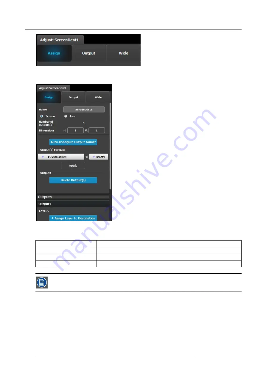
6. GUI orientation
•
Assign
•
Output
•
Wide
Assign Menu
•
Name: Adjusts the name of the Destination.
•
Destination type: Reports the type of destination Screen
or Aux. Can convert from Screen to Aux if it meets
requirements.
•
Number of output(s): Reports the number of output
con
fi
gurations in the destination.
•
Dimension: Adjust the output con
fi
guration layout .
•
Auto con
fi
gure Output format: Reads the EDID information
of the connected device to acquire its format. If more than
one device is connected to the destination, it reads the
format of the
fi
rst output. This feature is not available for
SDI outputs.
•
Output(s) format: Adjusts the output format of the
destination. This is applied to all outputs that are added into
this destination.
•
Outputs: Provides a list of the output con
fi
gurations
assigned to the Destination.
For Aux destinations, only 1 Output con
fi
guration is shown
or is allowed to be de
fi
ned. From this menu outputs can be
deleted or added as in the output con
fi
guration menu.
•
Layer (only applicable when Destination is a Screen). The
list shows the layers assigned to this Destination.
There are only sixteen 2K layers available in the system. Each “Assign Layer to Destination” uses 2 layer resources (as we are in
mix mode.) Therefore based on the Layer mode (set in the System Modi
fi
er Panel), the number of “Assign Layer to Destination”
varies. The table below shows the maximum number of mixable layer for each layer mode.
Layer Mode
Number of mixable layers
2K (Single link)
8
Dual Link
4
4K - UHD
2
Layers need to be assigned to destinations before sources can be added to the destination.
Output menu
The Output Menu contains 3 sub-menus:
Main
,
Color
and
Timing
. Adjustments in the Main and Timing menus are identical as in
the output con
fi
guration menu. In this menu, however, adjustments can be performed on all or on selected outputs that make up the
destination. Individual outputs can be selected by clicking on the corresponding screen. When a screen is selected its outline will
turn blue. All outputs can also be selected by clicking on the
Select All
button.
102
R5905948 E2 12/12/2014
Содержание Event Master E2
Страница 1: ...E2 User s guide R5905948 00 12 12 2014...
Страница 8: ...Table of contents 4 R5905948 E2 12 12 2014...
Страница 16: ...2 Safety 12 R5905948 E2 12 12 2014...
Страница 32: ...3 General 28 R5905948 E2 12 12 2014...
Страница 82: ...6 GUI orientation Image 6 8 78 R5905948 E2 12 12 2014...
Страница 94: ...6 GUI orientation Image 6 20 90 R5905948 E2 12 12 2014...
Страница 115: ...6 GUI orientation Image 6 37 Thumbnail view Image 6 38 R5905948 E2 12 12 2014 111...
Страница 186: ...7 System Setup 182 R5905948 E2 12 12 2014...
Страница 192: ...8 Updating firmware 188 R5905948 E2 12 12 2014...
Страница 196: ...9 General operation example Image 9 3 192 R5905948 E2 12 12 2014...
Страница 213: ...9 General operation example Image 9 25 R5905948 E2 12 12 2014 209...
Страница 216: ...9 General operation example 212 R5905948 E2 12 12 2014...
Страница 220: ...10 Maintenance 10 2 Process Overview Flow chart Image 10 2 216 R5905948 E2 12 12 2014...
Страница 226: ...10 Maintenance Image 10 11 2 Pull out the Front cover and lay it flat in front of the unit 222 R5905948 E2 12 12 2014...
Страница 281: ...10 Maintenance Disregard the heatsink from the spare kit R5905948 E2 12 12 2014 277...
Страница 282: ...10 Maintenance 278 R5905948 E2 12 12 2014...
Страница 286: ...11 Environmental information Republic of Turkey In conformity with the WEEE Regulation 282 R5905948 E2 12 12 2014...
Страница 288: ...11 Environmental information 284 R5905948 E2 12 12 2014...
Страница 298: ...B Remote Control Protocol 294 R5905948 E2 12 12 2014...
Страница 299: ...C Troubleshooting C TROUBLESHOOTING R5905948 E2 12 12 2014 295...
Страница 300: ...C Troubleshooting 296 R5905948 E2 12 12 2014...


