6. GUI orientation
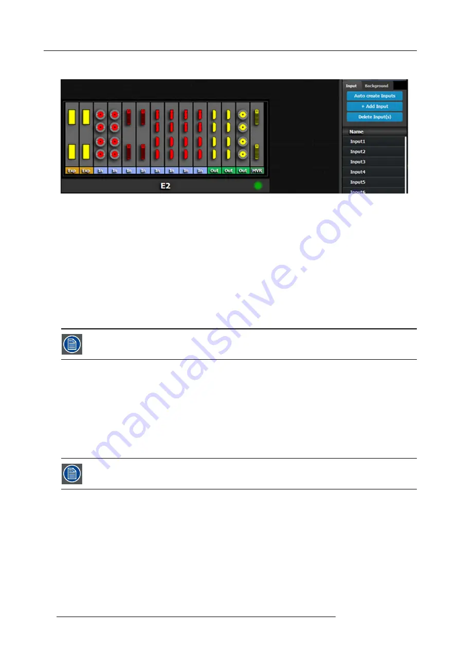
by default names inputs as “Input 1, 2, 3….” . Input con
fi
guration names can be renamed by double-clicking on the name and turning
the box blue.
Image 6-17
The auto create feature only creates 2K input. 3D and 4K Inputs need to be assigned manually. See
How to add Input
section
below.
How to add Input
Inputs con
fi
gurations can be added manually to un-assigned connectors.
1. Click on the
Add Input
button.
The
Add Input
button is replaced by the
Done Adding
button (highlighted in blue).
2. In the System diagram area, click on the connector(s) that need to be assigned.
Note:
If the input signal is 4K provided by the 4 SDI connectors, 4 SDI connectors need to be selected.
Connector(s) is immediately highlighted in blue.
3. The selection is completed by clicking the
Done Adding
button that is highlighted in blue.
A new Input is added in the input list.
To stop the add procedure without add new input, just click on the Done Adding button without selecting an
input.
How to delete Input
1. Click on the
Delete Input(s)
button
The
Delete Input(s)
button is replaced by the
Delete Selected
button (highlighted in red).
2. Click on the corresponding connector in the graphical area.
Or,
click in the “x” on the right hand side in the input con
fi
guration list.
Connector(s) is immediately highlighted in blue.
3. The deletion is completed by clicking the
Delete Selected
button.
Multiple connector con
fi
gurations can be selected to be deleted together.
How to access to the Input con
fi
guration adjustments
Adjustments to inputs are performed in the “Adjust” panel:
1. Select the input from the con
fi
guration list
Or,
clicking on the connector graphic.
An input is selected.
2. Click on the
Adjust
tab that is on the top of the Adjustment area.
86
R5905948 E2 12/12/2014
Содержание Event Master E2
Страница 1: ...E2 User s guide R5905948 00 12 12 2014...
Страница 8: ...Table of contents 4 R5905948 E2 12 12 2014...
Страница 16: ...2 Safety 12 R5905948 E2 12 12 2014...
Страница 32: ...3 General 28 R5905948 E2 12 12 2014...
Страница 82: ...6 GUI orientation Image 6 8 78 R5905948 E2 12 12 2014...
Страница 94: ...6 GUI orientation Image 6 20 90 R5905948 E2 12 12 2014...
Страница 115: ...6 GUI orientation Image 6 37 Thumbnail view Image 6 38 R5905948 E2 12 12 2014 111...
Страница 186: ...7 System Setup 182 R5905948 E2 12 12 2014...
Страница 192: ...8 Updating firmware 188 R5905948 E2 12 12 2014...
Страница 196: ...9 General operation example Image 9 3 192 R5905948 E2 12 12 2014...
Страница 213: ...9 General operation example Image 9 25 R5905948 E2 12 12 2014 209...
Страница 216: ...9 General operation example 212 R5905948 E2 12 12 2014...
Страница 220: ...10 Maintenance 10 2 Process Overview Flow chart Image 10 2 216 R5905948 E2 12 12 2014...
Страница 226: ...10 Maintenance Image 10 11 2 Pull out the Front cover and lay it flat in front of the unit 222 R5905948 E2 12 12 2014...
Страница 281: ...10 Maintenance Disregard the heatsink from the spare kit R5905948 E2 12 12 2014 277...
Страница 282: ...10 Maintenance 278 R5905948 E2 12 12 2014...
Страница 286: ...11 Environmental information Republic of Turkey In conformity with the WEEE Regulation 282 R5905948 E2 12 12 2014...
Страница 288: ...11 Environmental information 284 R5905948 E2 12 12 2014...
Страница 298: ...B Remote Control Protocol 294 R5905948 E2 12 12 2014...
Страница 299: ...C Troubleshooting C TROUBLESHOOTING R5905948 E2 12 12 2014 295...
Страница 300: ...C Troubleshooting 296 R5905948 E2 12 12 2014...


