background image

Chapter 3: Monochrome Terminals

Information Mode

MANU-MAXIMUS-02

Maximus Reference Manual

3-41

Revision-02

Information Mode

Information Mode

enables you to view the terminal firmware version, memory size,

hardware component versions, serial number, and Ethernet configuration settings.

You access the

Information Mode

from

ATS TSD Mode

. See

"ATS TSD Mode" on page 3-13

for information on accessing the

ATS TSD Mode

.

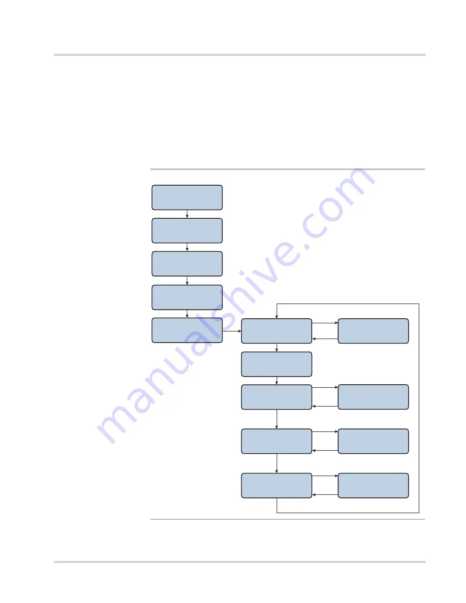
Figure 3-7

provides a flow chart of the

Information Mode

menu navigation.

Figure 3-7

Information Mode Navigation Flow Chart

ATS TSD Mode

Setup Mode

ATS TSD Mode

Download from USB

clear

clear

clear

ATS TSD Mode

Exit

enter

Information Mode

Version Info

enter

U-Boot: X.X.X

U-Boot: (Date)

clear

enter

RAM Total:  (XXX) k

RAM Free:  (XXX) k

clear

or enter

enter

Serial Number:

XXXXXXX

clear

or enter

ATS TSD Mode

Date/Time Setup

clear

Information Mode

Exit

clear

Information Mode

Memory Info

clear

Information Mode

Misc Info

enter

Host IP:

XXX.XXX.XXX.XXX

clear

or enter

clear

clear

Information Mode

Ethernet Info

clear

ATS TSD Mode

Information Mode

Содержание Maximus MCJ2000 Series

Страница 1: ...Reference Manual Your Trusted Partner for Time and Attendance Terminals and Integrated Solutions Maximus Reference Manual Part Number MANU MAXIMUS 02 Revision 02...

Страница 2: ...y of their respective owners Copyright Copyright 2015 by Accu Time Systems Inc All rights reserved Printed in U S A This publication and the software it describes contain proprietary and confidential...

Страница 3: ...Communication Acknowledgement 1 19 KeepAlives 1 19 DHCP 1 20 Chapter 2 Installation Installation Guidelines 2 3 Installation Choices 2 3 Wiring Distances 2 3 Terminal Wiring Access 2 5 Terminal Insta...

Страница 4: ...ete FP Templates 3 35 Reset Dnld 3 37 Download from USB 3 38 Date Time Setup 3 39 Information Mode 3 41 Version Info 3 42 Memory Info 3 43 Misc Info 3 44 Ethernet Info 3 44 Test Mode 3 46 Accessing Te...

Страница 5: ...Power Related Troubleshooting 5 10 Communication Related Troubleshooting 5 10 Appendix A Biometrics A 1 Why Use Biometrics A 3 User Confidentiality A 3 Reliability Rules A 3 ATS Biometric Operational...

Страница 6: ...S C 7 Using a USB Keyboard with the Terminal C 8 Appendix D GSM GPRS Setup D 1 Introduction D 2 Hardware D 2 Software D 2 Manually Configuring a GSM Terminal D 4 Enable PPP D 4 Set up a Provider Peer...

Страница 7: ...apter 2 Installation interests those responsible for the installation of the terminal or its wiring Chapter 3 Monochrome Terminals tells how to use the setup test and information menus in your monochr...

Страница 8: ...P 2 Maximus Reference Manual MANU MAXIMUS 02 Revision 02 This page intentionally left blank...

Страница 9: ...appear in non underlined blue text e g Chapter 2 Installation Bold Body Text Bold text in the document body text represents names and symbols that appear on the user interface screens For example Sel...

Страница 10: ...s document as the symbol Other text editors let you enter control characters by pressing the ALT key then entering the three digit decimal value Or you can write a custom application which inserts con...

Страница 11: ...This document may use warnings for various potential conditions The following are the warning formats with descriptions of their use This is how a note appears in this document NOTE This format is use...

Страница 12: ...Note Warning Formats P 6 Maximus Reference Manual MANU MAXIMUS 02 Revision 02 This page intentionally left blank...

Страница 13: ...of the Maximus terminal and lists its Part Numbers and specifications Chapter Contents This chapter contains the following topics Maximus Overview 1 3 Maximus Features 1 3 Specifications 1 5 Part Num...

Страница 14: ...1 2 Maximus Reference Manual MANU MAXIMUS 02 Revision 02 Chapter 1 Terminal Description This page intentionally left blank...

Страница 15: ...ports third party software and the needs of our partners for human capital management payroll data collection and workforce tracking Maximus Features The Accu Time Maximus terminal shown in Figure 1 1...

Страница 16: ...1 4 Maximus Reference Manual MANU MAXIMUS 02 Revision 02 Maximus Overview Chapter 1 Terminal Description Figure 1 1 Standard Maximus Terminal with biometric and swipe card readers l...

Страница 17: ...mming Java ATS Universal Command Set over Linux or third party custom application packages Web services enabled Diagnostics On board diagnostics and remote diagnostic capability Interfaces IEEE 802 3...

Страница 18: ...C 4 to 140 F Enclosure Die cast aluminum housing hinged to key lockable base Environmental Operating temperature 0 to 50 C 32 to 122 F Storage temperature 20 to 80 C 4 to 176 F Dimensions 21 33 cm x 2...

Страница 19: ...Function Keys MCS2000 XX Base Color Maximus UCS running on Linux OS 32MB RAM 32MB Flash Ethernet Host connection 320x240 transmissive LCD full color display 0 9 numeric keypad w Clear Enter and 8 Cus...

Страница 20: ...nsmissive LCD full color display 0 9 numeric keypad w Clear Enter and 8 Custom Function Keys With pin MXJ2100 XX Biometric Verification Java Maximus 1 1 E Field Fingerscan Reader 4K templates requires...

Страница 21: ...transmissive LCD full color display 0 9 numeric keypad w Clear Enter and 8 Custom Function Keys MXJ2101 XX Biometric Identification Java Maximus 1 N E Field Fingerscan Reader 500 templates no PIN req...

Страница 22: ...0 transmissive LCD full color display 0 9 numeric keypad w Clear Enter and 8 Custom Function Keys MXJ2105 XX Cogent Biometric Verification Java Maximus Cogent 1 1 Capacitive Fingerscan Reader 9K templ...

Страница 23: ...0 transmissive LCD full color display 0 9 numeric keypad w Clear Enter and 8 Custom Function Keys MXJ2106 XX Cogent Biometric Identification Java Maximus Cogent 1 N Capacitive Fingerscan Reader 1200 t...

Страница 24: ...0 transmissive LCD full color display 0 9 numeric keypad w Clear Enter and 8 Custom Function Keys MXJ2107 XX Suprema Biometric Verification Java Maximus Suprema 1 1 Capacitive Fingerscan Reader 9K tem...

Страница 25: ...0 transmissive LCD full color display 0 9 numeric keypad w Clear Enter and 8 Custom Function Keys MXJ2108 XX Suprema Biometric Identification Java Maximus Suprema 1 N Capacitive Fingerscan Reader 1200...

Страница 26: ...0 transmissive LCD full color display 0 9 numeric keypad w Clear Enter and 8 Custom Function Keys MXJ2111 XX Accu Touch Biometric Verification Java Maximus Lumidigm 1 1 Multispectral Fingerscan Reader...

Страница 27: ...0 transmissive LCD full color display 0 9 numeric keypad w Clear Enter and 8 Custom Function Keys MXJ2112 XX Accu Touch Biometric Identification Java Maximus Lumidigm 1 N Multispectral Fingerscan Read...

Страница 28: ...gnetic Stripe Track 2 with Infrared 97 2111 01 Cogent Capacitive Fingerscan 1 1 Not available for AccuTouch 97 2111 10 Suprema Capacitive Fingerscan 1 1 Not available for AccuTouch 97 2111 02 E Field...

Страница 29: ...terminal operation BASE EXT K06 Base Extension and Power Cover Table 1 3 Maximus Modules Part Number Description Table 1 3 page 2 of 2 Table 1 4 Maximus Accessories Part Number Description BASE EXT K0...

Страница 30: ...03 00 1 Foot Cable 63 2003 05 2 Foot Cable 63 2003 20 3 Foot Cable 63 2003 03 10 Foot Cable 63 2003 11 25 Foot Cable 63 2003 02 50 Foot Cable 63 2003 08 100 Foot Cable Cat 5 Ethernet Cable 8 conductor...

Страница 31: ...he terminal will continue from where it left off upon reconnection Upon reconnection the host also continues from where it left off except when the terminal resets In this case a power on message tran...

Страница 32: ...a Maximus terminal is connected to a network that has a DHCP server you can configure the terminal to its IP address from the DHCP server When a terminal configured to use DHCP comes online it querie...

Страница 33: ...es 2 3 Installation Choices 2 3 Wiring Distances 2 3 Terminal Wiring Access 2 5 Terminal Installation 2 6 Opening and Separating the Case 2 6 Mounting the Terminal 2 7 Main Components 2 10 Connections...

Страница 34: ...2 2 Maximus Reference Manual MANU MAXIMUS 02 Revision 02 Chapter 2 Installation This page intentionally left blank...

Страница 35: ...power to the terminal Wiring Distances The Maximus can communicate with a host computer in these ways 10 100 BASE T Ethernet standard RS232 option Dial up modem option When you have chosen a communic...

Страница 36: ...vision 02 Installation Guidelines Chapter 2 Installation Figure 2 1 Power Pack Location Requirements Mount 39 inches 99 cm from the Power Pack within 4 feet 122 cm of terminal bottom of the Maximus ba...

Страница 37: ...is equipped with a cable clamp that secures surface wiring routed through the recessed channel or fed through the lower conduit opening Choose the wiring method best suited to your installation Run r...

Страница 38: ...chassis lock location 2 Open the unit by pulling gently on the right hand edge of the terminal so it swings open on the hinges the terminal is hinged to the base on the left edge as you face it 3 If...

Страница 39: ...source you can mount the terminal on the wall 1 Choose a flat smooth interior wall for the terminal s location You will mount the Maximus using 4mm 8 pan head screws in four places Refer to Figure 2...

Страница 40: ...the three upper screws 4 Lower the mounting base onto the three upper screws then tighten them refer to Figure 2 6 on page 2 9 or Figure 2 7 on page 2 9 depending on if you separated the terminal or d...

Страница 41: ...AXIMUS 02 Maximus Reference Manual 2 9 Revision 02 Figure 2 6 Installing the Mounting Base with the terminal separated Figure 2 7 Wall Mounting the Maximus terminal not separated Mounting Screws Start...

Страница 42: ...section provides the locations of the main components inside the Maximus terminal Figure 2 8 shows the main components and modules locations with a Power over Ethernet module installed Figure 2 8 Maxi...

Страница 43: ...Maximus Main Board Connectors Biometric Reader Accu Touch WiFi Module Proximity Reader Board USB Ports Reboot Button Beeper Volume Control Beeper Speaker Debug Console Connector Option Board Connecto...

Страница 44: ...g CAT 5 unshielded twisted pair high speed data transmission cable with RJ45 plugs wired according to the EIA TIA 568B standard One end of the RJ45 terminated cable plugs into the Maximus Ethernet com...

Страница 45: ...56k Modem Connection If your Maximus is equipped with a 56k Modem Module plug one end of a standard RJ11 modular phone cable customer supplied into the socket on the module as shown in Figure 2 13 and...

Страница 46: ...ns with poor GSM signal reception Figure 2 15 shows how to connect install the 5 meter antenna Use the following procedure to install the 5 meter antenna 1 Disconnect the factory installed antenna fro...

Страница 47: ...or buzzers Two input connections provide contact monitoring The Maximus supports three types of optional DIDO modules 5 total Solid State Relay DIDO Modules 120 VAC 240VAC 60VDC Single Form C Relay M...

Страница 48: ...240 VAC Solid State DIDO Wiring Diagram Figure 2 17 provides a wiring diagram for the 60 VDC version of the module Figure 2 17 60 VDC Solid State DIDO Wiring Diagram FORM C DIDO Modules The DO functio...

Страница 49: ...o the DIDO module You may disconnect the terminal block s from the module then connect the wiring for the appropriate module as described in the previous section Plug the terminal block back into the...

Страница 50: ...tside of the Maximus outer case A second antenna equipped with a 5 meter cable Part Number 17 7005 00 provides flexibility for locations with poor WiFi reception Use the following procedure to install...

Страница 51: ...over Ethernet on page 2 19 UPS Battery The optional UPS battery backup system provides power if there is an interruption in power from the wall outlet Power Pack or PoE Choose the power source that i...

Страница 52: ...ng in case of extended storage periods The battery option includes a charger board which is a circuit board that installs in the terminal case and electrically connects the battery with the terminal s...

Страница 53: ...g fast charged It takes about seven hours to completely charge a fully drained battery Steady If the LED is lit steadily on The battery is fully charged The battery is too discharged to use fast charg...

Страница 54: ...2 22 Maximus Reference Manual MANU MAXIMUS 02 Revision 02 Power Connection Chapter 2 Installation This page intentionally left blank...

Страница 55: ...ower Up 3 4 Initial Setup 3 5 Initial Setup Menu Navigation 3 5 Initial Setup Parameters 3 7 ATS TSD Mode 3 13 Using the TSD Mode 3 14 ATS Setup Mode 3 15 Setup Mode Parameters 3 16 Re Boot 3 16 Setup...

Страница 56: ...t Info 3 44 Information Mode 3 41 Test Mode 3 46 Accessing Test Mode 3 46 Reader Test 3 47 Exit 3 47 System Diag Dump 3 48 Smart Card Test 3 49 Serial Test Direct 3 50 Serial Test Printer 3 51 LED Tes...

Страница 57: ...e and color Maximus are the same their setup menus are different You can differentiate between the monochrome and color Maximus without turning on the terminal The monochrome Maximus lens has a much s...

Страница 58: ...Universal Command Set UCS Version and the no longer applicable number of boards N A in the terminal as follows Table 3 1 lists the terminal type codes and the corresponding terminal descriptions Downl...

Страница 59: ...terminal will display the saved or default values for the terminal IP connectivity options In general press the enter key to accept the displayed value and go to the next option or press the clear ke...

Страница 60: ...Socket Port Socket Port 2500 Setup Addressing Type Dynamic DHCP Setup Addressing Type Static IP Setup Clock IP 000 000 000 000 Setup DNS IP 000 000 000 000 Setup Router IP nnn nnn nnn nnn Setup the Su...

Страница 61: ...to save the new IP address If you type an invalid IP address the terminal displays Bad IP Address and returns you to the saved default value Press the clear key again to correct the address then pres...

Страница 62: ...address When the terminal displays the desired option Dynamic DHCP or Static IP press the enter key to save the selection and continue to the next parameter If you changed to the Static IP option the...

Страница 63: ...rminal displays Bad IP Address Press the clear key again correct the IP address then press the enter key to continue 6 Next the terminal displays the Setup DNS IP parameter Press the enter key to acce...

Страница 64: ...If you type an invalid subnet mask value the terminal displays Bad IP Address Press the clear key again correct the value then press the enter key to continue 8 Next the terminal displays DHCP Option...

Страница 65: ...character and the clear key deletes the active most recently typed character When you are finished press the enter key to save the new name and continue Terminal Name ATS000001 Applications such as A...

Страница 66: ...of transmission EOT data If you choose Yes the terminal appends an ASCII EOT character 0416 to each transaction record sent to the host Press the enter key when the terminal displays the desired sele...

Страница 67: ...le password protection so only authorized persons can enter TSD mode See Setup Password on page 3 17 for details NOTE ATS TSD Mode Setup Mode Setup Host IP nnn nnn nnn nnn Setup Socket Port Socket Por...

Страница 68: ...ing the Restore Factory Settings command results in the Unable to Restore Settings response Download from USB See Download from USB on page 3 38 Date Time Setup See Date Time Setup on page 3 39 Inform...

Страница 69: ...ATS TSD Mode Download from USB enter clear clear clear enter enter re boots terminal clear ATS Setup Mode Re Boot ATS TSD Mode Date Time Setup clear ATS TSD Mode Information Mode clear clear ATS TSD M...

Страница 70: ...anges made to the setup parameters The terminal prompts you to re boot each time you enter Setup Mode 1 When you enter Setup Mode the terminal displays the Re Boot prompt Press the enter key to procee...

Страница 71: ...sword to restrict access to the terminal parameters e g initial setup TSD Mode Setup Mode 1 After you press the clear key at the Re Boot prompt page 3 16 the terminal displays the Setup Password param...

Страница 72: ...enter key at the to Setup Host Connect prompt to access the host connection options or press the clear key to proceed to the next item Setup Smartcard Confirm Password You must re boot the terminal i...

Страница 73: ...u selected Serial proceed to If you selected Serial for the Host Type on page 3 26 If you selected Ethernet for the Host Type 4 If you selected Ethernet for the Setup Host Type parameter the terminal...

Страница 74: ...e or Server Mode In client mode the terminal connects to the host server using the socket port as defined in the Setup Socket Port parameter In client mode the terminal makes the TCP IP connection to...

Страница 75: ...P address of the host then press the enter key to save the new IP address If you type an invalid IP address the terminal displays Bad IP Address and returns you to the saved default value Press the cl...

Страница 76: ...eed to ATS TSD Mode on page 3 13 The Static IP selection enables you to set the terminal to a permanent IP address The static IP address does not change until you type another one into the terminal Wh...

Страница 77: ...erminal displays Bad IP Address Press the clear key again correct the IP address then press the enter key to continue 11 Next the terminal displays the Setup DNS IP parameter Press the enter key to ac...

Страница 78: ...you type an invalid subnet mask value the terminal displays Bad IP Address Press the clear key again correct the value then press the enter key to continue 13 Next the terminal displays DHCP Option Co...

Страница 79: ...d selection Yes or No or press the clear key to toggle between Yes and No for support of end of transmission EOT data If you choose Yes the terminal appends an ASCII EOT character 0416 to each transac...

Страница 80: ...Type parameter that enables you to select either Modem or Direct Typically you select Direct when the host connects directly to the terminal In this case only one clock address applies 1 set via the E...

Страница 81: ...tup Smartcard The Setup Smartcard parameter enables you to define the storage capacity of an optional MifareTM or iClass contactless smartcard reader installed in the terminal if applicable installed...

Страница 82: ...pressed the enter key the first comm port parameter Select Baud Rate appears enabling you to set the baud rate for the port Press the enter key to accept set the displayed value or press the clear ke...

Страница 83: ...he Stop Bits parameter Press the enter key to accept set the displayed value or press the clear key to scroll between the 1 and 2 When finished press the enter key to save the setting and proceed to t...

Страница 84: ...press the enter key to access the Setup WiFi menu or press the clear key to proceed to the next item without configuring the WiFi device Device Type Device None You must select the correct type of de...

Страница 85: ...you enter the Setup WiFi menu the terminal displays the WiFi version When ready press the clear or enter key to proceed ATS Setup Mode Setup WiFi WiFi Signal Version X X X XXX If the WiFi unit is not...

Страница 86: ...enter key the terminal prompts you to confirm the reset Press the enter key to confirm the reset YES or press the clear key to cancel and return to the beginning of the WiFi menu 4 If you pressed clea...

Страница 87: ...l or press the clear key to proceed without disabling the device If you pressed the enter key the terminal prompts you to exit Press the enter key to exit the WiFi setup menu and return to the ATS Set...

Страница 88: ...rompt Press the clear key to proceed without setting the security encryption type or press the enter key to set the type If you pressed the enter key you can use the clear key to scroll between the WP...

Страница 89: ...to set the WiFi network SSID If you pressed enter the Set SSID prompt appears Use the keypad to type in the SSID WiFi network name then press the enter key to set the SSID and proceed The terminal re...

Страница 90: ...terminal prompts you if you want to proceed ERASE TEMPLATES Press the enter key to proceed or press the clear key to return to the Delete FP Templates parameter 3 If you pressed the enter key the term...

Страница 91: ...ey to exit the reset command or press the enter key to begin the reset If you pressed enter the terminal displays the CLEAR ALL MEMEORY Enter to Proceed confirmation prompt You can press the clear key...

Страница 92: ...y to install the download file application on the Maximus terminal For more information about the USB see Appendix C Using the USB For more information about the UCS applications downloads and dld fil...

Страница 93: ...ode menu Figure 3 6 Date Time Navigation Flow Chart Use the following procedure to change the terminal Date and Time 1 Go to the ATS TSD Mode and press the clear key until the Date Time Setup prompt a...

Страница 94: ...to change it If you pressed clear press the enter key to exit without changing the date or use the numeric keys to set the desired date you can use the clear key to delete the last number you entered...

Страница 95: ...rovides a flow chart of the Information Mode menu navigation Figure 3 7 Information Mode Navigation Flow Chart ATS TSD Mode Setup Mode ATS TSD Mode Download from USB clear clear clear ATS TSD Mode Exi...

Страница 96: ...er version information U Boot date of the boot loader version Kernel main operating system version Kernel main operating system version date Eeprom hardware driver version Eeprom hardware driver versi...

Страница 97: ...r key to proceed to the Exit prompt 4 Press the enter key to exit from the Information Mode menu and return to the ATS TSD Mode menu or press the clear key to proceed to the Memory Info prompt Memory...

Страница 98: ...C board number G 10 for the terminal Use the following procedure to enter the Misc Info menu 1 Press the clear key when in the Information Mode menu until the Misc Info prompt appears then press the e...

Страница 99: ...terminal Subnet Mask IP subnet mask used by the terminal Gateway IP IP address of the gateway router DHCP OptionCode DHCP option code e g 0 for pad set by protocol Mac Address Media Access Control ad...

Страница 100: ...e menu navigation Figure 3 8 Test Mode Navigation Flow Chart ATS TSD Mode Setup Mode ATS TSD Mode Download from USB clear clear clear ATS TSD Mode Exit ATS TSD Mode Date Time Setup clear ATS TSD Mode...

Страница 101: ...en ready press the enter key to start the test 3 Use the appropriate card on the terminal For example if the terminal is equipped with a magnetic stripe reader swipe the card The terminal responds by...

Страница 102: ...e results of the terminal tests in text file format to a USB flash drive plugged into the Maximus terminal Use the following procedure to run a System Diag Dump 1 In the Test Mode menu press the clear...

Страница 103: ...ss the clear key to exit the System Diag Dump and return to the Test Mode menu at the Smart Card Test option Smart Card Test The Smart Card Test option tests an optional MifareTM or iClass contactless...

Страница 104: ...rect Serial Test Direct This test requires specific loopback jumper and is typically only performed by an ATS service technician It is noted here for reference purposes 1 Install the jumper in the ser...

Страница 105: ...test The terminal reports that the test is in progress If desired you can interrupt and stop the test by pressing the clear key When the test is complete the terminal displays the result 4 When you a...

Страница 106: ...Press the enter key to initiate the test The terminal illuminates all the pixels on the LCD then briefly shuts them all off When the test is complete the LCD returns to the Test Mode Display Test opt...

Страница 107: ...ss the clear key until the System Test option appears 2 Press the enter key to select the System Test option The terminal prompts you to press the enter key to start the test Press Enter to Test 3 Pre...

Страница 108: ...er 3 Install a USB flash drive into the USB port then press the enter key The terminal displays the test result when the test is complete 4 When you are finished press the clear key to exit the USB te...

Страница 109: ...al is equipped with a UPS battery backup system and displays the result 4 Press the enter key to test the condition of the battery The system checks the battery and reports the result 5 Press the ente...

Страница 110: ...ed in the terminal Use the following procedure to test the optional modem 1 In the Test Mode menu press the clear key until the Modem Test option appears 2 Press the enter key to select the modem test...

Страница 111: ...to stop the test and exit to the Test Mode menu at the DIDO Test 1 option GSM Signal Strength This option only appears with a GSM GPRS module installed and used primarily when installing a 5 meter an...

Страница 112: ...to the GSM Signal Strength parameter then press it again to restart the test 4 Press the clear key to exit to the Test Mode menu when finished DIDO Test 1 The DIDO test checks the functionality of the...

Страница 113: ...DIDO test If you are finished press the clear key to exit to the Test Mode menu at the Keypad Test option You may now remove the jumper from the terminal Keypad Test The keypad test checks the functi...

Страница 114: ...en while illuminating the OK check LED for each correct key press 4 If you pressed the keys in the correct sequence and all the keys are functioning correctly the test self terminates and the system r...

Страница 115: ...to start the test The system prompts you to place your finger on the reader 4 Place your finger on the fingerscan reader sensor The system scans your finger then displays the result when finished e g...

Страница 116: ...3 62 Maximus Reference Manual MANU MAXIMUS 02 Revision 02 Test Mode Chapter 3 Monochrome Terminals This page intentionally left blank...

Страница 117: ...ter contains the following topics Color Display 4 3 Using the Configuration Menu 4 4 Initial Setup 4 6 Initial Setup 4 6 Test Setup Diagnostics TSD Menu 4 13 Setup Mode 4 15 Host Type 4 15 Common Sett...

Страница 118: ...4 2 Maximus Reference Manual MANU MAXIMUS 02 Revision 02 Chapter 4 Color Terminals This page intentionally left blank...

Страница 119: ...are the same their setup menus are different You can differentiate between the monochrome and color Maximus without turning on the terminal by looking at the lens The color Maximus lens has a much la...

Страница 120: ...iguration Menu Navigation The Main Menu displays the selections you can make To choose a selection press the corresponding function button on the terminal For example if you compare Figure 4 3 and Fig...

Страница 121: ...evision 02 Figure 4 3 Color Maximus Configuration Menu Initial Setup Menu Shown 03 12 18 Friday Nov 7 2014 Host IP Address Static IP IP Address Re Boot Set Date Time Reset Download FP Device Test Setu...

Страница 122: ...n is shown in Figure 4 3 on page 4 5 Host IP Address This sets the IP address of the computer with which the terminal communicates Press the F1 key to select the Host IP Address parameter The screen p...

Страница 123: ...nitial Setup menu displays the IP Address parameter that enables you to set the static IP address for the Maximus described in the following section IP Address The Initial Setup menu displays this par...

Страница 124: ...on places the terminal in setup mode described in Setup Mode on page 4 15 03 38 15 Friday Nov 7 2014 OK re start Return To Setup You have asked for a re boot or have changes that require re boot To re...

Страница 125: ...te Press the F1 key to display the Enter Date prompt screen as shown in Figure 4 8 Use the numbers on the terminal keypad to enter a new date then press the enter key The date uses the selected date f...

Страница 126: ...gure 4 9 Use the numbers on the terminal keypad to enter a new time then press the enter key Use a 24 hour format to enter the time even if the terminal displays time in 12 hour format e g key in 2105...

Страница 127: ...start Selecting this option reboots the terminal and applies any changes you have made Press the F8 key to select Return to Setup Selecting this option places the terminal in setup mode described in S...

Страница 128: ...u and go to the TSD mode screen Test Setup Diagnostics as shown in Figure 4 12 on page 4 13 This screen also enables you to access the Information Mode the Download from USB command and the Restore Fa...

Страница 129: ...vides access to the following selections Setup Mode Setup Mode F1 key provides access to all the configuration settings for the Maximus terminal except for factory service only settings See Setup Mode...

Страница 130: ...Settings This function is reserved for specific applications In typical Maximus configurations pressing the F5 key to select Restore Factory Settings command results in the Unable to Restore Settings...

Страница 131: ...Return To Setup from the Reboot Confirmation Window Setup mode has two screens one for serial host setup and the other for Ethernet setup see Figure 4 14 on page 4 15 and Figure 4 15 on page 4 16 Host...

Страница 132: ...n if your Maximus terminal is equipped with a Cogent reader and you want it to operate in Verification Mode Fingerprint Cogent Identify Select this option if your Maximus terminal is equipped with a C...

Страница 133: ...rd of up to seven digits for access to the terminal setup screens Use the following procedure to set a password 1 Press the F6 key to select Set Password 2 At the Enter New Password prompt type a new...

Страница 134: ...changes you made Return To Setup Selecting this option F8 key brings you to the Setup Mode Main Menu screen Serial Setup The Setup Serial and Comm Port menus enable you to customize the serial connec...

Страница 135: ...This selection does not time out 5 If the Maximus connects to a serial modem press the F3 key to select Auto Answer This parameter enables you to select 1 Ring 2 Rings 3 Rings or None no rings by pres...

Страница 136: ...You can press the clear key to delete a number With the desired number displayed press the enter key to accept the number This selection does not time out 8 Press the F8 key to select Return To Setup...

Страница 137: ...eter press the F3 key to scroll between the parity options of odd even and none The currently selected value displays in the middle of the screen The default value is odd 4 To change the value for the...

Страница 138: ...rnet connection 3 On the TCP IP Setup screen use the F1 key to select between TCP IP Client and TCP IP Server In client mode the terminal makes the TCP IP connection to the designated host computer Wh...

Страница 139: ...tted between devices The Append EOT No selection does not add append EOT numbers To change the displayed Append EOT value press the F6 key to select between Append EOT No and Append EOT Yes 6 To chang...

Страница 140: ...the center of the screen Figure 4 20 GSM PPP Setup Screen Configuring WiFi 1 To configure the WiFi interface if installed press the F8 key to select Setup WiFi PPP must be disabled before you can ena...

Страница 141: ...select Next F8 key to proceed If you selected Next the center of the screen displays Set Factory Defaults 7 If you want to return the WiFi interface to the factory default settings press the enter ke...

Страница 142: ...A for public standardization Some are used and some are not For example option 117 specifies the order in which name services should be consulted when resolving host name and other information Options...

Страница 143: ...cess the Secondary TCP IP Setup screen shown in Figure 4 23 The center of the Secondary TCP IP Setup Screen displays Host the host IP address Clk the IP address for the terminal Rtr the IP address for...

Страница 144: ...o the Secondary TCP IP Setup screen You can press the clear key to delete a number 3 To change the IP address for the Gateway router press the F3 key to select the Router IP Address parameter and to a...

Страница 145: ...Return to Setup This function appears in different menus and returns the terminal to the previous menu screen For example press the F4 key when in the TCP IP WiFi setup screen to return to the Host Ty...

Страница 146: ...reen as shown in Figure 4 25 Figure 4 24 Color Maximus Configuration Menu Initial Setup Menu Shown Figure 4 25 Test Setup Diagnostics Screen 03 12 18 Friday Nov 7 2014 Host IP Address Static IP IP Add...

Страница 147: ...the display reads Test Mode Reader Test to start the test When the display reads Test Reader or Wand use a card e g swipe or activate the wand Press the clear key or select Next to exit the test when...

Страница 148: ...s Test Mode GSM Signal Strength to start the test The test displays the signal strength of the cellular data network received by the GSM antenna Move the terminal antenna or both to change the receive...

Страница 149: ...t This lights all the LEDs on the terminal one at a time including those behind the lens and those on the keypad Press the clear key or select either Prev or Next when finished Serial Test Printer Thi...

Страница 150: ...e number of lines on the display Press the clear key to return to the Information Mode selections To exit Information Mode and return to the Test Setup Diagnostics menu cycle through the selections to...

Страница 151: ...Information Mode Ethernet Info to view the following network information Host IP IP address of the host computer that the terminal connects to Local IP IP address of the terminal Subnet Mask IP subne...

Страница 152: ...m of 224 colors can be used Some colors in the map are reserved for drawing the time digits which use 32 shades of gray The ssaver conf file has the following settings idletime Sets the number of seco...

Страница 153: ...ying Installation 5 3 Test Download File 5 3 Maintenance 5 4 Cleaning the Terminal 5 4 Cleaning the Badge Reader 5 4 Cleaning the Biometric Sensor 5 5 Caring for the Biometric Sensor 5 7 Troubleshooti...

Страница 154: ...5 2 Maximus Reference Manual MANU MAXIMUS 02 Revision 02 Chapter 5 Maintenance This page intentionally left blank...

Страница 155: ...terminal s response Test Download File Use a text editor capable of inserting control characters 000 through 03110 000 through 1716 to create a download file containing the lines The following comman...

Страница 156: ...e following instructions for cleaning badge and fingerprint readers Cleaning the Badge Reader To clean the badge reader swipe a cleaning card premoistened with isopropyl alcohol rubbing alcohol throug...

Страница 157: ...ry dirty you may need to repeat the cleaning operation using a new clean swab 5 After cleaning with the damp swab gently rub the surfaces again with a clean dry cotton swab 6 Reconnect the terminal po...

Страница 158: ...finger sensor by disconnecting the terminal from its power source 2 Using a new pink rubber pencil eraser remove the deposits tarnishing from the surface of the conductive ring do not use the eraser...

Страница 159: ...ion the sensor should not be exposed to rain or excessive moisture With the exception of the procedure as described in Cleaning the Biometric Sensor on page 5 5 do not put any liquids on the sensor Ne...

Страница 160: ...h host computer Terminal to Host communication cable is defective or unplugged on either end Verify cable is tested and plugged into both ends Ensure that cable termination guidelines and lengths are...

Страница 161: ...Monday through Friday Before contacting Accu Time please be prepared to provide the serial number and the configuration number of the product Terminal does not accept keypad input Keyed data does not...

Страница 162: ...Check the outlet both power pack connections and that it is a 12 VDC power pack Replace the power pack The low power yellow indicator LED is lit Outlet or power pack problem Check the outlet both pow...

Страница 163: ...s If parameters are set ping the terminal Verify that the cable is plugged into both ends terminal and hub and terminated to the appropriate eight position modular connector Verify that the single seg...

Страница 164: ...5 12 Maximus Reference Manual MANU MAXIMUS 02 Revision 02 Troubleshooting Guide Chapter 5 Maintenance This page intentionally left blank...

Страница 165: ...s Appendix contains the following topics Why Use Biometrics A 3 User Confidentiality A 3 Reliability Rules A 3 ATS Biometric Operational Options A 4 Verification and Identification Modes A 5 Verificat...

Страница 166: ...A 2 Maximus Reference Manual MANU MAXIMUS 02 Revision 02 Appendix A Biometrics This page intentionally left blank...

Страница 167: ...e or save the type of image file required by the Integrated Automated Fingerprint Identification System IAFIS The IAFIS is the national fingerprint and criminal history system maintained by the Federa...

Страница 168: ...ll Two Fingers ATS terminals enable you to configure the fingerscan device to require more than one fingerscan e g index and middle finger Override Verification for Individuals ATS terminals enable yo...

Страница 169: ...This is called Verification Mode It answers the question Am I the person I say I am Identification Mode 1 N Mode is also called Identification Mode This method confirms a person s identity by compari...

Страница 170: ...tional terminals When a person places his or her finger on the sensor the reader captures an image of the fingerprint From this point the reader finds unique patterns within the fingerprint The starti...

Страница 171: ...more susceptible to misreads caused by damage on the top layer of the skin Furthermore if only the surface layer of skin is examined the readers can also fall prey to gelatin duplicates of fingerprint...

Страница 172: ...nology is desirable for high resolution low cost imaging in normal environments Multi Spectral Imaging Technology Lumidigm The multi spectral reader uses different light wavelengths 430 530 630 nm and...

Страница 173: ...nsors use active capacitive pixel sensing technology to detect the finger ridge and valley patterns They measure the capacitance of the finger to obtain an image The capacitance of the finger changes...

Страница 174: ...th the skin surface subcutaneous structures Your internal fingerprint is identical to your external fingerprint as illustrated in Figure A 6 Figure A 6 Internal and External Fingerprint Source Lumidig...

Страница 175: ...rent images taken on a single reader during a single finger placement offers the following advantages Multiple authentication images at enrollment and during authentication Multiple scanning wavelengt...

Страница 176: ...n finger positioning Users should center the bottom of their first joint on the placement guide before lowering their finger onto the sensor Figure A 9 shows the placement guide in front of an E Field...

Страница 177: ...he display shows the acceptance rejection message e g Your finger has been accepted Figure A 11 Correct Finger Placement on a Finger Scanner Side View Sensors Without Placement Guides Many multi spect...

Страница 178: ...tication Issues Common issues that produce a rejected authentication are Position Placing your finger far from the center position of the sensor will increase the rejection rate Rotation Finger rotati...

Страница 179: ...MANU MAXIMUS 02 Maximus Reference Manual A 15 Revision 02 Appendix A Biometrics Finger Placement Figure A 13 Correct and Incorrect Finger Placements Position Rotation Pressure...

Страница 180: ...A 16 Maximus Reference Manual MANU MAXIMUS 02 Revision 02 Finger Placement Appendix A Biometrics This page intentionally left blank...

Страница 181: ...ed with Maximus terminals that can be equipped with optical barcode and or magnetic stripe readers Appendix Contents This Appendix contains the following topics Optical Barcode Badges B 3 Guidelines B...

Страница 182: ...B 2 Maximus Reference Manual MANU MAXIMUS 02 Revision 02 Appendix B Badge Specifications This page intentionally left blank...

Страница 183: ...be greater than 75 for light in the 600 to 880 nanometer wavelength range The minimum width of a narrow barcode element should be 0 010 inch The ratio of wide to narrow bar code elements depends on th...

Страница 184: ...l MANU MAXIMUS 02 Revision 02 Optical Barcode Badges Appendix B Badge Specifications Figure B 1 Typical Barcode Position Sizes optional holes for clips shown as dotted lines 211904 35 50 25 min quiet...

Страница 185: ...n the Maximus terminals Physical Specifications Figure B 2 shows the physical dimensions and positions for magnetic stripe badges used with the Maximus terminals Figure B 2 Typical Magnetic Stripe Pos...

Страница 186: ...provides a graphical representation of the fields in Track 1 and Table B 2 provides a description of the fields Figure B 4 Card Data Format Track 1 223 110 Recording Density bits inch 110 110 Track 1...

Страница 187: ...etionary Data Number of characters PVKI Pin Verification Key Indicator 1 PVV or Offset Pin Verification Value 4 Card Verification Value CVV or Card Validation Code CVC 3 Some or all of the PVKI PVV CV...

Страница 188: ...Value 4 Card Verification Value CVV or Card Validation Code CVC 3 Some or all of the PVKI PVV CVV and CVC fields may be found with the Discretionary Data Table B 3 Card Data Format Track 2 Field Desc...

Страница 189: ...nterchange Controls 1 PAN Service Restriction 2 SAN 1 Service Restriction 2 SAN 2 Service Restriction 2 Expiration Date optional 4 Card Sequence Number 1 Card Security Number optional 9 Additional Dat...

Страница 190: ...ludes The maximum facility code is 255 which is the decimal equivalent of setting all eight facility code bits to one The maximum card number is 65 535 which is the decimal equivalent of setting all s...

Страница 191: ...ppendix This Appendix describes how to use a portable USB drive with your terminal Appendix Contents This Appendix contains the following topics Overview C 3 What You Need C 3 Functions C 3 Applying a...

Страница 192: ...C 2 Maximus Reference Manual MANU MAXIMUS 02 Revision 02 Appendix C Using the USB This page intentionally left blank...

Страница 193: ...unctions You can use a portable USB drive to do the following Apply a download dld file to the terminal see Applying a Download on page C 4 Store punches and transactions when the terminal is disconne...

Страница 194: ...nal downloads and applies it to the terminal If there are more than one dld file in the root directory of your USB drive the terminal lists the download files for you to navigate between Press E to se...

Страница 195: ...S40 see the Universal Command Set UCS Reference Manual Part Number MANU UCS 01 If the terminal is disconnected from the network then you can save the following transactions and punches to the USB driv...

Страница 196: ...ing 18 numbers and the extension usb such as yymmddhhmmssNNNNNN usb such as 080229150528000090 usb where yy the last two digits of the year the file was created mm the month the file was created dd th...

Страница 197: ...your portable USB drive 2 Safely remove the USB drive from your computer 3 Plug the USB drive into the USB connector on the terminal 4 Put the terminal in Setup Mode 5 Reboot the terminal 6 The update...

Страница 198: ...terminal and perform all the same functions on it as you can on the terminal keypad On the standard USB keyboard F1 through F8 operate the terminal s F keys the Backspace key operates the terminal s C...

Страница 199: ...endix Contents This Appendix contains the following topics Introduction D 2 Hardware D 2 Software D 2 Manually Configuring a GSM Terminal D 4 Enable PPP D 4 Set up a Provider Peer Configuration File D...

Страница 200: ...he GSM modem 2 Open the terminal and plug the GSM modem into the serial connection 3 Feed the antenna cable from the outside of the terminal case through the antenna hole into the interior of the term...

Страница 201: ...ce provider in the Provider or Service Provider menu The host computer needs to have an Internet facing IP address and any firewall needs to permit communication on the port selected for the terminal...

Страница 202: ...d chat scripts in these directories on your terminal etc ppp peers etc ppp directories To enable PPP log on to the terminal and use the following command echo pppEnabled 1 dev atsconfig To disable PPP...

Страница 203: ...ink you can set up the new provider There are three components that make up a complete provider configuration the peer file the chat script and the authentication information In order to create these...

Страница 204: ...d File The PPP password file is found here etc ppp pap secrets Open and modify this file to include the username and password combination you want for your connection The username is the same one you...

Страница 205: ...ires you enter 4 1 900MHz or 1800MHz requires you enter 5 1 etc ppp cat connect yourchatfilename ABORT BUSY ABORT NO CARRIER ABORT ERROR ATV1 OK AT WOPEN 0 OK AT WMBS 5 1 OK AT CGDCONT 1 IP wap endpoi...

Страница 206: ...gnal strength and wireless connectivity 1 Make sure PPP is enabled for the terminal 2 Make sure a configured provider has been selected for the terminal 3 Select Test Mode on the terminal 4 In Test Mo...

Страница 207: ...Stripe Guidelines B 5 Optical Barcode B 3 Proximity B 10 Barcode Optical Badges B 3 battery 1 5 2 19 battery backup 2 12 2 20 5 10 baud rate 4 21 Biometric Deleting Finger Templates Setup Menu 3 36 P...

Страница 208: ...st Configuration Protocol See DHCP dynamic mode TCP IP 4 25 E EIA 1 3 Encoding Magnetic Stripe Badges B 6 end of transmission See EOT enter key 3 14 EOT 4 23 setting to No 3 12 3 25 4 23 setup 3 12 3...

Страница 209: ...3 M Magnetic Stripe Guidelines for Badges B 5 Maintenance Cleaning Biometric Sensor 5 5 maintenance 5 4 badge reader 5 4 cleaning terminal 5 4 making selections in setup mode 3 14 manual audience P 1...

Страница 210: ...1 Setup Menu Delete FP Templates Command 3 36 setup mode 3 16 flow diagram 3 6 sequence of screens 3 6 setup mode parameters 3 16 sleeptime 4 36 Smartcard 3 27 4 21 socket port 3 7 3 21 4 29 Space Cha...

Страница 211: ...ns See punches TSD mode 3 13 3 14 two way communication 1 19 U UCS sample 5 3 updating from USB C 7 updating UCS from USB C 7 USB applying a download C 4 storing punches C 5 updating UCS C 7 what you...

Страница 212: ...Index IX 14 Maximus Reference Manual MANU MAXIMUS 02 Revision 02...

Страница 213: ...This page intentionally left blank...

Страница 214: ...Reference Manual Your Trusted Partner for Time and Attendance Terminals and Integrated Solutions Maximus Reference Manual Part Number MANU MAXIMUS 02 Revision 02...

Отзывы: