


Musca-S1 development board and Musca-S1 test chip power rails
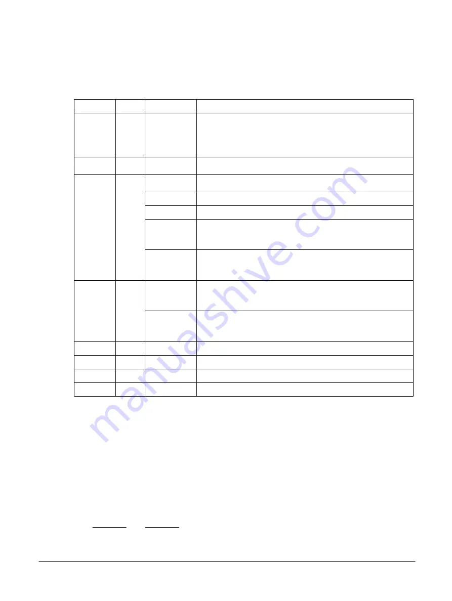
The following table shows the maximum loads that the Musca
‑
S1 development board power rails draw
from the power supplies.
Table 2-4 Musca-S1 development board and Musca-S1 test chip power rails
Power rail
Voltage Max load (mA) Comment
DHUB5V
5V
500
1000
Standard USB 2.0.
Some USB 2.0 charging ports permit up to 1000mA.
Combined Shield and board current must not exceed the USB current limit.
VBAT
4.2-3.3V 500
Lithium-ion battery, when charging
3V3
3.3V
30
DAPLINK and SoC
2
I2C sensors (Gyro/Temp/ADC)
15
QSPI
900
Shield 3V3 (USB)
Combined Shield and board current must not exceed the USB current limit.
400
Shield 3V3 (battery)
Combined Shield and board current must not exceed the battery current limit.
ARD_5V
5V
900
Shield 5V (USB).
Combined Shield and board current must not exceed the USB current limit.
250
Shield 5V (battery).
Combined Shield and board current must not exceed the battery current limit.
VDD_CORE 1V0
150
SoC core supply
VDD_IO
1V8
100
SoC I/O supply
VDD_PLL
1V8
5
PLL VDD low power
VDD_XTAL 1V0
1
XTAL VDD
External power
The DAPLink 5V USB connector supplies all external power to the Musca
‑
S1 development board.
Backup battery
A backup battery can power the Musca
‑
S1 development board, using the connector on the lower face of
the board.
Arm recommends using the Lithium Ion, CLN 523450, 3.7V, 950mAh battery. The battery is recharged
from an external supply during USB 5V operation. If a battery is fitted while external power is
connected, circuitry on the board automatically charges the battery with a maximum charging current of
500mA.
Jumper links select the power source, 5V USB or battery, for the board and the Shield.
Note
• Jumper link J18 selects the board power to be either USB or battery.
• Jumper link J19 selects the Shield power to be either USB or battery.
2 Hardware description
2.8 Power
101835_0000_01_en
Copyright © 2019, 2020 Arm Limited or its affiliates. All rights
reserved.
2-35
Non-Confidential


