background image


Chapter 1 – General information / Technical specifications 


Service Manual AJP PR3/PR4                                                                                                        1 - 45 


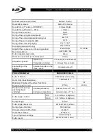
Current consumption 

12,8V 1,95A 

Frequency  

80Hz (+-10Hz) 

Operating temperature 

10

o

C – 30

o

C


(-20

o

C


– 55

o

C) 

50

º

F – 86

º

F (-4

º

F – 131

º

F) 

Starting time 

Lower than 1 second 

Off time 

Lower than 1.5 seconds 

Average lifetime 

100 Hours 


Horn 

Klaxon 12V DC 

Operating voltage 

12V (+/-2V) 

Current consumption 

<1,5A 

Sound intensity (dB) 

100dB (+/-5dB) at 2 meters 

Frequency 

460Hz (+/-30Hz) 

Durability 

50.000 Cycles 


Ignition system 

CDI (Capacitive Discharge Ignition) 

CDI unit 

MD125 – 3B 

Coil Ignition 

MGO3A // MGE3B (ZXF-130727) 

Resistance of the primary ignition coil 

3,5Ω - 4,5Ω 

Secondary resistance without coil plug 

3,0KΩ - 5,0KΩ 

Secondary resistance with coil plug 

8,0KΩ - 12,0KΩ 

Spark plug cap 

NGK LB05F / VD05F / YB05F 

Spark plug cap resistance 

5KΩ 

Ignition coil cable 

Ø7x470mm 

Ignition spark plug (standard) 

LG D8TC 

Ignition spark plug (equivalent) 

CHAMPION A8YC / NGK DR8ES / DPR8EA-9 

Distance between the electrodes 

0,6 – 0,7mm 

Spark plug thread pitch 

M12x1.25 

Spark plug torque 

1,8Kgf.m (18N.m) 

Pulse generator (pick-up) 

100Ω - 150Ω 

Phase of the pick-up 

Blue / white wire 

Pick-up neutral 

Green / white wire 

Distance between pick-up and the ridge on the 

wheel 

0,7mm (+/-) 

CDI drive coil 

Black / red wire 

Resistance exciter coil of the CDI 

230Ω - 350Ω 


Содержание PR4

Страница 1: ...dical attention immediately Keep children and pets at a distance DANGER Gasoline is extremely flammable and explosive under certain conditions KEEP IT AWAY FROM CHILDREN Components with high temperatures DANGER The engine and exhaust system are hot when the engine is running and maintains this high temperature sometime after the engine stops Use insulated gloves or wait for the engine to cool befo...

Страница 2: ... nitrogen under high pressure Should never be near a flame or heat source since there are explosion hazards that can lead to serious injury Charging a damper with nitrogen carries a risk of explosion which can lead to serious injury if the damper is incorrectly heated or bored To avoid risk of explosion open the valve mechanism and release nitrogen The remaining oil should be treated according to ...

Страница 3: ...ate 1 is placed in front of the frame on the left side It has marked the approval number the serial number of the frame and the sound level at a specified rotation TABULATED INFORMATION In the following tables are information on technical data and specifications of the bikes AJP PR3 and PR4 As additional help may also be included some specifications for the previous models versions PR3 PR4 WARNING...

Страница 4: ...05 intake 0 08 exhaust Intake valve Opens at 5o BTDC Closes at 30 o ABDC Exhaust valve Opens at 35 o BBDC Closes at 5o ATDC Ignition Electronics by CDI Initial advance of the spark angle 10o BTDC 2 000 100rpm Full advance of spark angle 30 o BTDC 4 000 100rpm Spark plug standard LG D8TC Spark plug equivalents CHAMPION A8YC NGK DR8ES DPR8EA 9 Gap between the electrodes 0 6 0 7mm Gear box 5 speed Cl...

Страница 5: ...gip i Ride Moto SAE 20W 50 API SG JASO MA MA2 Main oil filter Reusable metal mesh thimble type Engine oil replacement The first change should occur at 500Kms Then every 2000Kms Cooling Air Air and oil Air and oil Oil cooler motor 200 240 GR 125 MOTORCYCLE DIMENSIONS PR4 2001 2007 Element PR4 EN TR PR4 SM PR4 SM M Wheelbase 1410 1320 Seat height 920 910 905 Fuel tank capacity 9 Liters Weight dry 99...

Страница 6: ...filter Rotor on the crankshaft 125 200cc Ø68mm 240cc Ø58mm Checking the oil level Display on the right engine cover Oil pump Mandate drive gear 125 1st version Z39 nylon Z37 nylon 200 240 Z37 steel with cover Pump rotors 125 Outside 8 teeth 23x13mm Inside 7 teeth 200 240 Outside 5 teeth 23x13mm Inside 4 teeth Clearance in the tip 0 15 0 20 Clearance in the body 0 15 0 21 0 35 Clearance in the end ...

Страница 7: ...il pipes Short pipe output Bolt 10mm or 8mm tightens on the engine crankcase Bolt 12mm tightens down on oil cooler Long pipe input Screw M10 or M8x1 tightens on the clutch cover Bolt 12mm tightens on top of the oil cooler Sealing washers 8mm 8 2x14 5x1 5 Sealing washers 10mm 10 2x16x1 2 Sealing washers 12mm 12 3x20x16 CYLINDER HEAD VALVES VALVE MECHANISM Element Item Specification Service limit Cy...

Страница 8: ...055 0 10mm Mark on the valves DC Ø Valves hat IN 125 30mm 200 31 5mm 240 34mm EX 125 25mm 200 26mm 240 28 5mm Total height of the valves IN 125 91mm EX 125 90 3mm IN 200 240 91 5mm EX 200 240 90 7mm Valve seat width IN EX 1 1 1 3mm 1 5mm Groove height of the retaining loops 125 150 3mm 200 240 5mm Retaining loops position 125 150 Up 200 240 Down Valve springs Length size IN EX Inside 39x17 5x12 5m...

Страница 9: ...right side Bushing 20x28x11 Valve mechanism Timing chain 125 4x98 Links 200 7x100 Links 240 7x10² Links Sprocket 125 Z34 200 240 Z34 Valve mechanism pinion Z17 Mounting position of the pinion on the crankshaft Tooth aligned with the keyway Sprocket fixing screws 125 M6x10 200 240 M6x12 Valve mechanism guide chain tensioner 125 Short 175mm 200 Medium 240 Long Timing chain tensioner 125 200 240 Ref ...

Страница 10: ...6 470 56 490 56 40 mm 150 kit 60 970 60 990 60 80mm 200 240 68 970 68 990 mm 10 mm from the bottom of the skirt 68 80 mm Clearance cylinder piston 0 010 0 040 0 20 mm Piston pin 125 Ø15x10x48 150 kit Ø15x10x50 200 240 Ø17x12x55mm Inside diameter of the pin hole 125 15 002 15 008 15 04mm 200 240 17 002 17 008 17 04mm Outer diameter of the pin came 125 14 994 15 000 14 96 mm 200 240 17 994 17 000 16...

Страница 11: ...crankshaft 210mm Threaded on the right side M16x1 Threaded on the left for the flywheel 1st version M8x1 25 or M10x1 Connecting rod radial clearance 0 000 0 008 0 05mm Connecting rod lateral clearance 0 05 0 30 0 80mm Connecting rod lateral clearance on the crankshaft 0 60mm Backhand Stroke of the crankshaft 0 03mm Pin size rod crankshaft 30x54mm Bearing of the connecting rod foot side 30x38x18mm ...

Страница 12: ...ecting rod 18mm Pin in the connecting rod crankshaft Ø32x54mm Bearing of the connecting rod foot 32x41x18 Dimensions of the rollers Ø4 5x14 7mm GEAR BOX Element Specification Service limit Gear box ratio Primary transmission By gears 125 Engine Primary reduction Z73 Z18 4 055 1st secondary primary Z36 Z13 2 769 2nd Z32 Z17 1 882 3rd Z28 Z20 1 400 4th Z26 Z23 1 130 5th Z24 Z25 0 960 200 Engine Prim...

Страница 13: ...200 Z32 23 020 23 041 C2 240 Z28 22 020 22 041 C3 Z28 Z23 22 020 22 041 C4 Z26 Z21 20 020 20 041 C5 Z24 Z21 20 020 20 041 Bushings in the secondary gears C1 16 5x19 5x7 3 I D 16 516 16 534 O D 19 479 19 500 C2 22x25x10 not existing in 240 engine I D 22 000 22 021 O D 24 979 25 000 Starter sprocket 16 5x20x7 8 O D 19 959 19 980 Outer diameter primary shaft M5 Z13 Z11 19 959 19 980 Outer sleeve guid...

Страница 14: ...haft 11 966 11 984 11 90 O D shaft gearshift linkage 14 CLUTCH FOUR CLUTCH SPRINGS ENGINES 125 200Cm3 Item Specifications Service limit Engines equipped with four clutch springs ZS156FMI 2A 125Cm3 ZS169YML 200Cm 3 Number of clutch plates coated 5 Thickness of the coated discs 3 0mm 2 85mm Inside diameter of the coated discs 91mm Outer diameter of the coated discs 109 5mm 110mm The ridges outer dia...

Страница 15: ...f the screws on the table 1 2Kgf m 12N m Clutch fixing on the primary shaft Castle nut M16x1 Locking ring with retaining tabs engine 200 240 Mounting position of the taper washer Outside out Clutch nut torque 93 N m 9 5 Kgf m Clutch thrust bearing 16003 Stud pressure Simple FIVE CLUTCH SPRINGS ENGINES 125 200Cm3 Item Specifications Service limit Engines equipped with five clutch springs ZS156FMI 2...

Страница 16: ... the plate on the five springs hub With aligned points Total thickness of all the five clutch springs 35 2mm 34 8mm Springs dimensions Ø18 5x35 2x13 3 Normal length of the springs 35 2mm 33 3mm Pressure plate screws M6x22 Tightening torque of the screws on the plate 1 2kgf m 12N m Clutch fixing on the primary shaft Castle nut M16x1 Locking ring with retaining tabs engine 200 240 Mounting position ...

Страница 17: ...ness 3 4mm 3 30mm Hub height in grooved zone 31 1mm Outside diameter of the grooved central ridge 39 95mm Hub height aluminum 38 85mm Total height of the hub clutch 40mm Hub pressure plate outer diameter 110mm Thickness of the pressure plate 9 0mm 8 85mm Inside diameter of the hole in the pressure plate 40mm Height of the threaded bolts on the six springs plate 32 1mm Diameter of M5 bolts Ø10 7mm ...

Страница 18: ...cs 1 00mm thickness BEARINGS SEALS WASHERS AND ENGINE BOLTS Component Dimensions Crankshaft bearings 63 28 C3 28x68x18 Right crankcase bearing on the primary shaft 6006 Left crankcase bearing on the primary shaft 6202Z Left crankcase bearing on the secondary shaft 6204 Right crankcase bearing on the secondary shaft HK152315 Thrust bearing in the clutch 16003 Bearings bushings of the start up reduc...

Страница 19: ...1 washer on the primary shaft 15 2x25x1 Sprocket ribbed washers on the gears shaft 20x17 3x26x1 6 Starter sprocket washer on the primary shaft 20 5x27x0 5 Starter sprocket washer on the secondary shaft 15 2x30x1 Washer at the end of the kicks shaft 12 2x17 9x1 Washers of the shaft in the startup reductions 10 5x17 7x0 5 Distance washer from the clutch sprocket 240 30x42x0 5 Washer pitch of the clu...

Страница 20: ... up 14mm Clearance between the stator and flywheel 1mm Manufacturer reference of the neutral position T Manufacturer reference of the ignition point advance F Rotational direction of the magnetic flywheel Counterclockwise Flywheel fixing bolt on the crankshaft M8x1 25x35 or M10x1x40 Washer of the flywheel bolt 8 5x24x3 5 or 10 5x23 6x2 4 M8 bolt tightening of the flywheel M8 32 m 3 2Kgf m M10 bolt...

Страница 21: ... 4mm Brush springs 2 Magnetic housing 2 Magnets 4 Magnets Outer diameter of the magnetic housing 62 5mm 62 5mm Inside diameter of the housing magnets 41 8mm 46 8mm Length of the magnetic housing 67mm Brushes screw terminal square head M6x25 Terminal screw internal insulator Bakelite square Terminal screw external insulator bushing Bakelite round Ò ring outer sealing of the terminal screw 5x2 Insid...

Страница 22: ...r of the tsprocket on the sprocket starter 54 20mm 42 20mm 0 2mm Inner diameter of the sprocket bushing 20 or 22mm 22mm 0 1mm Distance ring from the sprocket to the crankshaft Ø20 20 2x31 8x3 5 Distance ring from the sprocket to the crankshaft Ø22 22 1x34x3 5 Starter clutch In the flywheel 3 cylindrical roller One way bearing Starter clutch rollers 10 2x11 5 mm 10mm Spring rollers 3 85x30 mm 25mm ...

Страница 23: ...ES Element Specification Service limit Outlet pipe between tank filter Ø9x5x220mm Outlet pipe between filter pump Ø9x5x220mm Outlet pipe between pump bypass T Ø9x5x170mm Supply pipe between T carburetor Ø9x5x60mm Return pipe between T tank Ø9x5x385mm Vacuum pipe between pump nozzle inlet Ø9x5x210mm Gasoline filter IDEAL 6mm ...

Страница 24: ... 110 105 110 Idle jet 50 50 45 45 50 45 48 48 Air screw 1 5 turns 2 turns 3 4 turn 1 turn 2 turns 1 5 turns 2 5 turns 1 5 turns Needle Bridle 1st slot 3rd slot Piston Needle 125KA AAA 125KA AAA CC Needle diffuser M7x M7x 5 5 2 2 Top diffuser Ø2 66 cylinder Accelerator piston O1C Ø22 CO Ø24 O1C Ø22 CO Ø24 O ring phalange 29x2 5 34x2 29x2 5 34x2 33 5x2 5 Float K 22 8 SF 172 2 K 22 8 SF 172 2 Valve s...

Страница 25: ...haft table PR4 fork Marzocchi 40mm M20x1 5 Washer of the screw triple clamp shaft Marzocchi 40mm 20x40x3 Washer of the lower bearing PR4 Marzocchi 40mm 25x35x1 5 Triple clamp screw Marzocchi 40mm M8x40 w phalange Triple clamp tightening Marzocchi 40mm 22N m 2 2Kgf m Screws of the handlebar clamps on triple clamp Marzocchi 40mm M10x60 w nut Handlebar clamps on triple clamp tightening Marzocchi 40mm...

Страница 26: ...s finishing Black DLC coating Diameter of the fork 45mm Dimensions of the fork Ø45x500mm Cover fork torque 30N m 3 0Kgf m Tightening of the pipes fork in door axis 150N m 15Kgf m Seals retainers 45x58x11 Dust seals scrapers 45x58 5x13 Fork springs 435mm Dimensions of the springs Ø40x30 5x435mm Wire thickness of the springs 4 5mm Springs constant K 45 N m 4 6Kgf mm Preload plug of the springs 25mm ...

Страница 27: ...rs 36x48 5x13 Quantity of oil in the hydraulic 300ml Recommended oil type ENI AGIP Fork SAE 10W Fork springs 560mm Dimensions of the springs Ø29x560x21mm Wire thickness of the springs 4mm Springs constant K 40N mm 4 1Kgf mm Preload plug of the springs H 70mm Dimensions of the preload plug Ø30x70x24mm Limit spring extension 27mm Cover forks M32x1 5 Hexag 22mm O ring in the fork cover 26x3 5 Tighten...

Страница 28: ...ptional Polisport DTR 125 type PR4 EN SM TRAIL fork 2001 2010 PAIOLI 41mm Type Hydraulic Maximum stroke 260mm Height between the cover of the forks and the wheel axle 890mm 3 Forks Ø41mm hard chrome Dimensions of the forks Ø41x700x36mm Seals retainers 41x53x10 5 Seals scrapers 41x53 5x13 Quantity of oil in the hydraulic 430ml Oil level with fork whole down 190mm Recommended oil type ENI AGIP Fork ...

Страница 29: ...ndlebar clamps UNI 5931 M8x30 Torque of the handlebar clamps 25N m 2 4Kgf m Wheel axle fixing bolts DIN 912 M6x35 Torque of the wheel axle retaining screws 10N m 10Kgf m Bellows protection of forks optional Polisport DTR 125 type PR3 EN PRO MX SM TRAIL fork 2012 FASTACE Fork type Up Side Down 38mm Forks Ø38mm chrome Dimensions of the forks 38x545mm Passage hole in the oil forks 4 Ø5mm Tubes of the...

Страница 30: ...istance between the adjuster on the rod and fork cover 81 5mm O rings seals of the adjuster in the fork cover 4 5x1 9 Ball fixer of the adjuster position 3mm Rod needle aluminum hydraulic regulation Ø4x45x433mm Hydraulic cartridge tube M22x1 Ø25x390x22 Valve thread pitch on the cartridge tube M12 Oil quantity in each fork 355ml Recommended oil AGIP FORK SAE 5W Function of the fork adjusters In the...

Страница 31: ... cartridge M12x1 Ø12x590 aluminum M12x1 adjustment nut on the rod end 27mm of the tip top Hydraulic adjustment rod Ø5x577mm aluminum Distance sleeve on the rod Ø25x120x12mm Regulation of the preload adjusting nut 10mm away from the nylon bushing Lower fixation screw DIN 912 M10x30 Lower sealing ring Ø10x16x1 5 copper Recommended oil AGIP FORK SAE 10W Fork oil capacity each fork 430ml Fork adjustme...

Страница 32: ...escent 130mm Standard regulation Return up 10 Cliques since all loosened Compression down 16 Cliques Since all tight Load setting of the springs External Adjuster on the forks covers All rotated to the left PR4 EXTREME Fork MARZOCCHI 48mm Forks of the fork Ø 48x592mm DLC coating Outer forks tubes Bordeaux 569x59x54X48 Maximum Warping of the tubes forks fork 0 2 Spring length no load 475mm 465mm Pr...

Страница 33: ... FORK SAE 7 5W Hydraulic oil for softer suspension AGIP FORK SAE 2 5W Oil capacity in each cartridge 210ml Oil capacity of the fork in each fork 340ml Minimum 300ml Maximum 400ml Oil level in the forks with return bar fully extended and without compression group 140mm Adjusters function In the center of the cover Return Triangular PFP Preload At the foot of the fork Compression Adjusters full stro...

Страница 34: ... connecting rod PR4 2001 2006 long Steel zinced Frame connecting rod bearings HK1814RS Frame connecting rod bushing 18x10x65 Frame connecting rod washer Nylon 29x18 Swing arm connecting rod PR4 2001 2006 Steel zinced Swing arm connecting rod bearings HK2020RS Swing arm swing arm connecting rod bushing 20x12x50 Swing arm swing arm connecting rod washers 31x20x2 5 Frame connecting rod PR3 PR4 2007 A...

Страница 35: ... mm Gas pressure in the reservoir 981KPa 10Kgf cm2 Type of gas in the Shock absorber reservoir Nitrogen Shock absorber adjustment for high speed compression external adjuster in the reservoir 12 Clicks after all tight Shock absorber regulation at low speed compression adjuster inside the reservoir 8 Clicks after all tight Shock absorber regulation in return hydraulic brake bottom adjuster along th...

Страница 36: ...Maximum shock absorber stroke 40mm Stroke stop height 20mm Adjusting nut M40x1 Fixation pin of the adjusting nut M5x10 Spring dimensions 45x70x170mm Spring length no load 170mm Absorber spring preload standard 163mm Spring constant 56N mm Lower fixing screw M10x50 WHEELS AND TYRES Element Specification Service limit Tires PR3 MX Front 70 100 19 Rear 100 100 16 PR3 EN TRAIL Front 70 100 19 Rear 100...

Страница 37: ...J21x1 60 DOT 36T Left drilling Rear J18x2 15 DOT 36T Left drilling PR4 SUPERMOTO Front J17x2 50 DOT 36T Left drilling Rear J17x3 50 DOT 36T Left drilling PR4 SPECIAL EDITION EXTREME Front 1 60x21 36T Rear 2 15x18 36T Rim wheel warpage Radial 0 2 Axial 2 0 Front tire pressure cold ENDURO TRAIL MX 150kPa 1 5Kgf cm2 SUPERMOTO 175kPa 1 75Kgf cm2 EXTREME SPECIAL EDITION ULTRAPASSAR 120kPa 1 20Kgf cm2 1...

Страница 38: ... TRAIL UNISON black PR4 EXTREME AJP MORAD Bordeaux Length of the front wheel spokes PR3 EN MX TRAIL 238x3 8mm PR3 SM 207x3 8mm PR4 EN 240x3 8mm PR4 SM 195x3 8mm PR4 EXTREME 245x3 5mm Amount of the front wheel spokes PR3 32 PR4 36 Bend angle of the spokes PR3 wheels MORAD 8º PR4 wheels UNISON 12º PR4 wheels EXTREME 10º Wrench size to adjust the spokes 5 9mm 5 4mm PR3 PR4 front wheel bearings 6004 2...

Страница 39: ...mm fork Left disc side 19mm Right side 23 5mm Rear Wheels Length of the rear wheel spokes PR3 SM Right 207x3 8mm Left 210x3 8mm PR3 EN Right 212x3 8mm Left 215x3 8mm PR3 MX Right 195x3 8mm Left 207x3 8mm PR4 EN Right 210x3 8mm Left 207x3 8mm PR4 SM Right 192x3 8mm Left 189x3 8mm PR4 EXTREME Right 192x3 8mm Left 198x3 8mm Rear wheel spokes number PR3 32 PR4 36 Bend angle of the spokes PR3 wheels MO...

Страница 40: ...ub 28x3 Rear hub seals PR4 EN SM TRAIL Disc side 30x47x7 Sprocket side 30x47x7 PR4 EXTREME Disc side 30x42x7 Sprocket side 30x47x7 Rear wheel bushings PR3 Disc side 7 5mm Disc side 2015 5mm Sprocket side 14mm PR4 MORAD hub Sprocket side 20mm galvanized iron Sprocket side 11mm galvanized iron Caliper support 16 5mm thick PR4 EN SM TRAIL Ultrapassar Disc side 12mm aluminum Sprocket side 27mm aluminu...

Страница 41: ... Right 6 2mm Until the slit or 1mm before the steel plate Left 6 4mm Brake calipers PR3 Front 2 Pistons Ø 25mm Rear 2 Pistons Ø 32mm or 2 Pistons Ø 25mm PR4 Front 2 Pistons Ø 25mm Rear 4 Pistons Ø 25mm or 2 Pistons Ø 25mm Brake calipers type Floating Brake pipes PR3 2007 2010 Front 1170mm Rear 570mm PR3 2010 2014 Front 1160mm Rear 600mm PR4 2001 Front 1210mm Rear 460mm PR4 SM S Front 1045mm Rear s...

Страница 42: ...AILING Black Oil level display Front eyepiece Pump repair kit Ø 11mm piston Retention of the piston in the pump With elastic ring Brake lever Black without adjuster PR4 2013 BRAKING aluminum Oil level display Front eyepiece Pump repair kit Ø 11mm piston Retention of the piston in the pump With elastic ring Brake lever Short polished with adjuster PR4 2014 BRAKTEC aluminum Oil level display Front e...

Страница 43: ...version M10x1x21 PR3 PR4 2014 BRAKTEC w display short cover Distance between fixing holes 49mm Piston diameter Ø 12 7mm Repair kit of the cover diaphragm pump AJP Racord screw M10x1x21 Sealing washers 10x14x1 5 copper Stop light switches Front Mechanical M6x0 8 Rear Hydraulic M10x1 ELECTRIC SYSTEM Item Specification Electrical system 12 Volts Main fuse PR3 PR4 20A yellow plug type Fuse PR3 MX norm...

Страница 44: ...al socket M5x5 Magnet on the front brake disc Magnetic tablet Ø 6x6mm Mounting position of the magnet With the N facing the speedometer sensor Battery YTX5L BS Type Sealed MF Battery capacity 12V 4A Battery electrolyte quantity 0 24Liters Electrolyte package ECR 0 24E Specific electrolyte H2SO4 sulfuric acid at 41 Specific weight of the electrolyte 1 32kg C at 20o C Battery Maintenance Maintenance...

Страница 45: ...Coil Ignition MGO3A MGE3B ZXF 130727 Resistance of the primary ignition coil 3 5Ω 4 5Ω Secondary resistance without coil plug 3 0KΩ 5 0KΩ Secondary resistance with coil plug 8 0KΩ 12 0KΩ Spark plug cap NGK LB05F VD05F YB05F Spark plug cap resistance 5KΩ Ignition coil cable Ø7x470mm Ignition spark plug standard LG D8TC Ignition spark plug equivalent CHAMPION A8YC NGK DR8ES DPR8EA 9 Distance between...

Страница 46: ...phasic half wave Manufacturer s Code MT12V8 Z05B XFT1QO7 111126 Model manufacturer XF0510 XIANFENG Connector for connection to wiring Sumitomo 6 way female port Charge coil line Yellow pink wire Charge line output to the battery red wire Negative line rectifier Green wire Current return line Black wire and green wire Starter relay MQJ10 ZSO1B 12V70A Solenoid resistance in the relay 3 5Ω 4 0Ω Start...

Страница 47: ...n the connector Headlight Maximum lights Blue On the left Medium lights White On the center Ground Black On the right Minimum Lights Brown Rear taillight Night light White On the top Stop light Blue In the middle Ground Black On the bottom TURN SIGNALS CONNECTIONS Component Turn signals color wires Wiring harness color wires Front turn signals Right Red Purple Green Left Yellow Green White Black G...

Страница 48: ... thread and the surface of the phalange 3 Apply clean engine oil to the O ring 4 Grease the thread and the surface of the phalange Note Reading the dimensions of the screws M6 Screw with metric thread M6 M6x16 Screw with metric thread M6 and 16mm length M6x16 x1 Screw with metric thread M6 16mm length and 1mm pitch Not all the screws have all the specified measures Only a few of them were specifie...

Страница 49: ... in the valve mechanism 1 M8 10 1 0 Adjustment nuts of the valves rocker arms 4 M6 15 1 5 Retaining plate screw of the valves rocker arms shaft 1 M6 12 1 2 Drive pinion Drive pinion screw cover 2 M6 12 1 2 Plate bolt to brake the drive pinion 2 M6x12 10 1 0 Cylinder Piston Cylinder stud 4 M8 19 1 8 2 Screw of the valve mechanism chamber 1 M6 10 1 0 2 Clutch Embraiagem Clutch cover screws 11 M6 12 ...

Страница 50: ...he problems inadvertently caused if this pin spring of the shift selector is removed from the crankcase FRAME Item QTY Dimensions mm Torque N m kgf m Note Frame beams Exhaust system Top fixing screw of the beams 8 M6x20 12 1 2 Lower fixing screw of the beams 2 M10x40 39 4 0 Screw securing the exhaust pipe 1 M8x20 32 3 3 Screws fixing the exhaust protection 2 M6x8 8 0 8 Exhaust manifold nut 1 M6 w ...

Страница 51: ...p stainless steel 4 M8x20 32 3 3 Screws fixing the lower triple clamp stainless steel 4 M8x20 13 1 3 3 Front wheel shaft aluminum 25 1 M20 x1 5 74 7 5 Fixing screw of the front wheel shaft 4 M6 w tab 12 1 2 Screws of the front brake disc 6 M6x16 12 1 2 Front axle fixing screws 4 M6x30 w tab 12 1 2 Rear wheel suspension Shaft nut of the rear wheel 1 M14 x1 5 93 9 5 Sprocket Screws 6 M8 32 3 3 Disc ...

Страница 52: ...f the front caliper bracket 1 M8 26 2 7 Rear brake pump cover screws 2 M4x12 1 5 0 15 Rear brake pump fixing screws 2 M6X20 10 1 0 Nut of the brake pedal kneecap 1 M8 20 2 0 Stud nut pitch of the rear pump 1 M8 20 2 0 Nut pivot bolt of the rear brake pedal 1 M8 20 2 0 Stud retention of the rear caliper pads 1 M10 20 2 0 Guide pin A of the rear brake caliper 1 M8 26 2 7 Guide pin B of the rear brak...

Страница 53: ... the O ring the contact surfaces All the sealing s Piston pin Molybdenum disulfide oil mixture of engine oil and mass of molybdenum disulfide Slot of the fork gear M3 M4 C5 on the drum Hole of the connecting rod pin Lobes of the camshaft Friction surface of the rocker arms Friction surface and contact area of the adjusting screw Valve guide friction surface Valve stem friction surface Outer surfac...

Страница 54: ...he fork seals Oil fork Brake pumps DOT 4 brake fluid Seals of the brake calipers Pistons and cylinders of brake calipers Pistons boxes in the brake pumps Between the front brake pump and the brake lever adjustment screw Silicone grease Slide surface of the brake lever pin Between the rear brake pump and the brake pedal adjustment screw Sliding area in the holes of the support pins guides in suppor...

Страница 55: ...ffler are not in contact with any other component of the motorcycle such as the fuel tank the rear brake pipe the stop switch cable or the carburetor tub breathing tube TROUBLESHOOTING Excessive exhaust noise Broken exhaust system Leakage in the exhaust system Low performance Deformed exhaust system Leakage in the exhaust system Clogged muffler FRONT HEADLIGHT REMOVAL Remove the front brake tube w...

Страница 56: ... and front turn signals according to the following displayed image FRONT FENDER REMOVAL Remove the screws and washers 1 Remove the fender INSTALLATION Installation is in the reverse order of removal Tighten the screws NOTE Check the tightening of the screws holding the front fender to the lower triple clamp before assembling the front fender again SIDE COVERS REMOVAL Remove the screws and washers ...

Страница 57: ...ove the front grids 2 INSTALLATION Installation is in the reverse order of removal Be careful when installing new front grids not the break in the bend zone Tighten the screws with the M6 nuts SEAT REMOVAL Loosen the screw 1 without losing the nylon bushing underneath the seat base Pull the seat back towards the fender to release it INSTALLATION Check if the seat hook 3 is aligned with the frame p...

Страница 58: ... light 1 Remove the screws 1 and the plate 2 Pull the fender towards the rear to release it INSTALLATION Installation is in the reverse order of removal Fit electrical connectors and check the operation of the turn signals and tail light NOTE Always use screws with the correct length M6x12 not to damage the fuel tank It should not be exceeded the specified torque when tightening the side covers of...

Страница 59: ...ing figure although the clamping points are the same the difference lies only in the existing rubber support in the back and fit within the cradle tube and that is to disassemble this protection has to pull forward to remove it INSTALLATION Installation is in the reverse order of removal Note that in the case of PR4 EXTREME first rubber should be fitted within the support cradle and thereafter rep...

Страница 60: ...ning screw 1 of the exhaust tube in the right beam Remove the screws fixing nuts of the flange on the exhaust tube Pull the curve 3 toward the front until you exit the exhaust chamber and pass the flange out of frame tube to be able to remove the tube INSPECTION Check for damage to the flange of the tube and sealing gasket If necessary straighten the flange of the curve to ensure a perfect seal on...

Страница 61: ...haust tube When setting the exhaust system first point the screws on the flange of the cylinder head Then the fixing screw of the curve on the right frame beam Always tighten first the tube nuts in the cylinder head and then the screw to fix the curve to the right beam Install the exhaust muffler In the end put the engine running and check for leaks in the exhaust system after installation Correct...

Страница 62: ...pport stand so that the two wheels rest against the ground LEFT BEAM REMOVAL Remove the seat and side covers of the front and rear Remove the air filter 1 Remove the air filter box with the intake pipe in rubber included 2 Release the fuel supply 3 in the fuel filter Release the return pipe in the flange of the fuel tank Remove the exhaust muffler If so loose the clamp fixing the motor stator cabl...

Страница 63: ...ted space to loosen or tighten correctly the four 6mm self locking nuts by the inside of the beam Remove the frame reinforcement screw in the left beam with 13mm box key machined in reduced outer diameter 17 5mm Remove the M10 nut of the screw of the upper shock absorber fixation with 17mm box key machined in reduced outer diameter 21 5mm Remove the screw fixing the bottom of the beam to the frame...

Страница 64: ...haft swing arm 14mm 88 N m 9 0Kgf m RIGHT BEAM REMOVAL Remove the seat and side covers of the front and rear Remove the air filter housing with the rubber intake pipe included Release the fuel supply tube in the gas filter and the return pipe in the fuel tank Remove the exhaust muffler and remove the screw in the fixing curve Disconnect the connectors of the taillight spoiler and rear turn signals...

Страница 65: ...s in reverse order of removal FRAME Replacement If it s necessary to replace the steel frame remove the crankcase protection and put the motorcycle resting on a bench appropriate support stand so that the two motorcycle wheels rest against the ground NOTE Before disassembling the components can be beneficial to take note or photos of the position of the various components especially electric cable...

Страница 66: ...e CDI Remove the rectifier current regulator and the turn signals relay if it exists Remove the battery Remove the battery holder Release the spark plug cable and the cable of the starter Remove the frame reinforcement with the ignition coil the petrol station and the horn ...

Страница 67: ...200 or 240 cm3 Remove the carburetor Release the vacuum tube in the intake manifold of the air intake Remove the intake manifold Remove the engine Front suspension removal Remove the nut of the steering column below the handlebar use a 32mm special key downgraded to a thickness of 9 5 mm in the case of forks SACHS or MARZOCCHI 48mm and untighten the four screws at the top of the triple clamps ...

Страница 68: ...shock absorber Remove the swing arm assembly with the damper the chain the rear wheel and the rear brake installed Remove the frame beams with the side stand the skates and the respective holders INSPECTION Check all the disassembled components and replace any part that is damaged INSTALLATION For the new frame In first place install the tracks boxes bearing tapered on the steering column Install ...

Страница 69: ...scribed on the beam installation section Tighten the horn and the fuel pump in the same fixing screw Install the oil cooler having regard to the mounting position of the spacer bushings and fixing screws in the case of motor 240cc as shown in the following image Tighten the banjos of oil tubes carefully not to damage the radiator Make sure that the oil cooler is not in contact with the cylinder he...

Страница 70: ...necting rod on the new frame Install the set of the swing arm with the wheel the chain and the rear brake as the reverse of disassembly Continue the installation of the remaining components in the reverse order of removal Assemble the rear section with the tank and fenders included Connect the fuel hoses and electrical connectors DANGER After perform all assembly operations perform a static and dy...

Страница 71: ...ystem are hot when the engine is running and maintains this high temperature for some time after the engine stop Use insulated gloves or wait for the engine to cool down before handling the engine or exhaust system Used engine oil Follow the laws in force in your country for collecting and treatment of waste oil Never dump used oil into the sewer or ground The oil is extremely toxic and contaminat...

Страница 72: ...e friction surfaces before proceeding to its assembly 6 After installation check that all parts are installed correctly and working MAINTENANCE SCHEDULE A description of the various maintenance operations required for the proper functioning of the motorcycle and the respective periods is presented next WARNING An intensive motorcycle driving with high revs tracks with mud or dust requires cleaning...

Страница 73: ...k the operation of the side stand Lubricate the steering column bearings Lubricate the bearings of the connecting rods and the swing arm bearings on the rear suspension Check the value of the empty voltage and the load voltage Check the condition of the exhaust system Check the condition and operation of the various components of the electrical system Check the condition and operation of the ignit...

Страница 74: ...heck the brake pads Replace the brake fluid Replace the timing chain Check the spoke tightness Check slack on the wheels Check the operation of the side stand Replace the oil from the fork Lubricate the steering column bearings Lubricate the bearings of the connecting rods and the swing arm bearings on the rear suspension Check the value of the battery s empty voltage and the load voltage Check th...

Страница 75: ...tion Tighten or replace Seat Fixing and security Tighten or replace the lock or its fixing rivets Clutch discs Proper operation and wear Replace Air filter Contaminated torn Clean or replace Emergency engine switch Correct functioning Fix it or replace Bolts nuts Correct tightening Tighten Valve clearance Correct clearance Adjust Timing chain Excessive noise Replace Spark plug Tightness correct te...

Страница 76: ...il to the maximum level mark H Place the engine and let idling for three minutes Stop the engine and check the oil level OIL CHANGE OIL FILTER DANGER Waste motor oil may cause skin cancer if they repeatedly get in contact with the skin for extended periods It is recommended to wash your hands with soap and water immediately after having handled waste oil Note Replace the engine oil with the engine...

Страница 77: ...r seal faced to the engine inside housing as shown in the following figure Install the oil filter case and tighten with the specified torque DANGER Putting the oil filter in a wrong position can lead to serious engine damage Tightening torque 25N m 2 5Kgf m Clean the oil glass Introduce by the oil filler cap the correct quantity of the recommended engine oil Note Use an appropriate funnel to put t...

Страница 78: ... suffer serious damage Use a small screwdriver to straighten the fins in the radiator honeycomb if necessary If the tubes or the oil cooler are damaged or with irreparable leaks they must be replaced immediately If replacement is necessary it should be consulted the procedures in Chapter 4 Lubrication System CENTRIFUGAL OIL FILTER The centrifugal filter 1 is located on the crankshaft on the right ...

Страница 79: ...ice and blow with compressed air all the components during the assembly Note When the bike is washed avoid direct pressure water jets directly to the air filter After washing use compressed air to dry the bike components Remove the air filter clean it and lubricate it Removal Remove the seat see Chapter 2 Frame Panels Exhaust Remove the fixing screw 1 and remove the cover over the air filter if it...

Страница 80: ...ilicone sealing in the filter casing cover should be replaced whenever dust indications are observed inside If the air filter box is damaged deformed on the fitting profile with the cover should be replaced to avoid causing excessive and premature wear to the valves cylinder and the engine piston ring Removal Remove the four screws and disassemble the air filter box Remove any existing silicone in...

Страница 81: ... position as shown in the following image and tighten gently to avoid damaging the rubber tube Note Do not over tighten the clamps as in the case of the clamp to tighten the filter housing may damage the same as in the case of tightening the carburetor may cause the rubber tube to jump out of the carburetor inlet fitting Assemble the air filter in the correct position on the box and tighten the fi...

Страница 82: ... obstruction of jets resulting in difficulties to put the engine running or inadequate handling of the vehicle When the bike is washed avoid direct pressure water jets directly to the breather in the cap of the fuel tank Fuel filter The fuel filter is transparent this allows to see the presence of impurities inside Always replace the fuel filter at the intervals specified in the Maintenance Schedu...

Страница 83: ...ength in order to avoid damage the tank when it is assembled in the rear frame Specific screws type oval head M6x12 Tightening torque 10N m 1 0Kgf m DANGER If the fuel tank is damaged it must be replaced immediately The use of the motorcycle with a damaged tank can cause fuel leakage to the rear wheel or cause a fire Check the connections of the fuel lines to the fuel tank pipe for the fuel pump 1...

Страница 84: ...e is extremely flammable and explosive under certain conditions KEEP IT AWAY FROM CHILDREN Work in a well ventilated area with the engine stopped Do not smoke do not let flames or cause sparks in the work area or where the fuel is stored Clean immediately any fuel spillage THROTTLE CABLE For smooth operation the cable and the inside of the throttle grip should be kept clean and lubricated so it sh...

Страница 85: ... is an engine which idle speed is correctly regulated is more easily to start Velocidade do ralenti 1400 Rpm 100 For more details on the technical specifications and adjustment of the carburetor see the table Specifications for the Regulation of Carburetors presented in Chapter 1 General Information Technical Specifications As for disassembly procedures cleaning assembly and adjustment of the carb...

Страница 86: ... clearance of the lever decrease SPARK PLUG Removal Note Before removing the spark plug clean thoroughly around it using compressed air and make sure that no foreign material is introduced into the combustion chamber Disconnect the spark plug cap 1 checking their condition and the cable from the ignition coil that connects it if any of this is not in good condition it should be replaced Remove the...

Страница 87: ...ue of the spark plug Apply a higher torque value can damage the threads in the cylinder head or make it impossible to subsequent removal of the spark plug VALVE CLEARANCE Note Inspect and adjust valve clearance when the engine is cold below 35 C Procedure Remove the seat and side covers Remove the air filter box and the intake pipe included Remove the right front grille Remove the throttle piston ...

Страница 88: ...s dashes in the camshaft gear must be aligned parallel to the face surface of the cylinder head For 125 150cc engines the reference mark that exists in the camshaft rack is an O which must be facing up upright and aligned with a cutout in the form of V existing on the outside of the cylinder head Check clearance on both valves through a feeler gauge between the adjusting screw and the auxiliary ha...

Страница 89: ...adjustment on the exhaust valve Loosen the lock nut 1 and enter the blade of the feeler gauge Tighten the set screw 2 until you have a slight friction in the feeler gauge 3 Tighten the fixing nut Check the clearance value and repeat the operation if necessary until the specified clearance Hold the fixing screw and tighten the fixing nut Tightening torques Intake 24N m 2 4Kgf m Exhaust 26N m 2 6Kgf...

Страница 90: ... the timing control point cover 3 and tighten gently until the value of the specified tightening Tightening torque Screws of the camshaft cover 12N m 1 2Kgf m Cover of the crankshaft 8N m 0 8Kgf m Timing control point cover 6N m 0 6Kgf m DRIVE CHAIN DANGER Be extremely careful not to put your fingers between the sprocket and the chain Stop the engine Lift the rear wheel by placing a support or box...

Страница 91: ...is actuating Always perform this operation to ensure that the rear brake is operational When the chain is too dirty it should be removed and cleaned before being lubricated Removal Remove the pinion cover 1 Remove the chain retaining clip 1 carefully Remove the fixing link Remove the chain WARNING Be careful not to lose the O rings when the clip and the retaining link are removed Wash the chain wi...

Страница 92: ... wear out quickly Assembly Install a new drive chain Place the fixing link and the retaining clip always facing the rotational direction of the chain and wheel Install the pinion cover Adjust the clearance of the drive chain DANGER Do not install the drive chain in without the four O rings of the fixing link Check that there is no clearance between the fixing link and the retaining clip Note Assem...

Страница 93: ...ve the motorcycle with faulty suspension Loose damaged or worn components may affect the stability and driving control FRONT SUSPENSION Check the operation of the fork compressing it several times 5 to 10 as shown in the following figure Check if the fork has signs of leakage or damage Replace all components that are damaged and or irreparable Confirm the tightness of all the screws and nuts to th...

Страница 94: ... the back of the bike several times 5 10 as shown in the following figure Check that all components of the rear suspension have been properly installed and that they are not damaged Confirm the tightness of all the screws and nuts to the specified torque Put the motorcycle on a stand or box to lift the rear wheel off the ground Try rotating the wheel sideways to check if the swing arm bearings are...

Страница 95: ...remove the clearance of the steering stem bearings Pay attention not to over tighten or you may prevent the free rotation of the steering Tighten the nut 2 and check the clearance again and that the handlebar turns freely Tighten the screws of the upper triple clamp 1 according to the specified torque value Tightening torque Steering table nut 98N m 10 0Kgf m Screws of the top table 32N m 3 3Kgf m...

Страница 96: ...lignment with the axis to check for clearance in swing arm Check if the tires are damaged or high wear Check if the wheels have corrosion or damage FRONT WHEEL REMOVAL Removal To remove the front wheel put the motorcycle resting on its frame on a stand so that the front wheel is off the ground WARNING Do not operate the front brake lever while the front wheel is removed ENDURO SUPERMOTO Unscrew th...

Страница 97: ...f the wheel turns freely without any hindrance Press several times the brake lever to make sure that the brake is operating Tightening torque Front wheel shaft 74N m 7 5Kgf m Fixing screws of the front wheel shaft 12N m 1 2Kgf m DANGER After assembling the front wheel operate several times the front brake lever to restore pressure in the system Keep the brake discs free of oil and greasy materials...

Страница 98: ...an lead to an unstable behavior of the motorcycle BRAKE SYSTEM Brake discs Due to wear the thickness of the brake discs in the contact area 1 with the pads decreases In its thinnest point A the difference in thickness with respect to the nominal thickness may not be larger than 0 5 mm Measure the nominal thickness in the area B outside the contact area and check in several points of the disc DANGE...

Страница 99: ...e cap from the front or rear brake while the handlebar is not in a position where the reservoir is level and the motorcycle upright Avoid acting the brake lever with the cover removed The brake oil will spill if the lever is actuated Do not mix oils since they may not be compatible Avoid spilling oil on painted parts plastic or rubber Place a cover in those parts whenever an intervention in the br...

Страница 100: ...ontact with the exhaust due to the vertical movement of the swing arm or to be crushed between the swing arm and the pump brake Brake pads replacement Front wheel Remove the brake caliper holder of the fork removing the two fixing screws 1 Press the caliper piston to move away and retract in order to be able to put the new pads Remove the clips retaining bolts then remove the pads from the caliper...

Страница 101: ...of the front brake pads brake lever should be actuated several times to restore the pressure in the system Rear wheel To remove the rear brake pads except for the case of PR4 EXTREME rear wheel must be removed see REAR WHEEL REMOVAL in this chapter After removal pads should be pushed with a key for this purpose in order to place the piston in its retract position Remove the retaining bolt 1 and th...

Страница 102: ...0N m 2 0Kgf m Rear brake pedal Adjustment Loosen the lock nut 2 Turn the adjuster stud 3 to increase or decrease the pedal height Measure the distance between the ball and the pump fixing bolt 4 If you have the correct measure 5 tighten the locknut STANDARD 93 0mm Standard regulation of the distance between the locknut of the adjustment stud and locknut on the kneecap of the brake pedal 6 12 5mm S...

Страница 103: ...de stand the motorcycle should not be inadvertently handled since the side stand may retract and lead to the motorcycle falling The PR3 PR4 side stand is designed to support only the motorcycle s weight At any time someone should sit when the motorcycle is supported on the side stand because this inappropriate effort may damage the side stand and their support and in extreme cases damage the left ...

Страница 104: ...e bottom of the muffler and with a Ø3 mm drill to unbolt and remove the rivets on the muffler terminal Separate the core of the aluminum profile and check if it is in good condition Inspect the perforated tube for damage If it is broken weld it to correct the failure Remove muffler end Remove any existing fiber inside the exhaust muffler Install ceramic wool blanket wrapping it correctly around th...

Страница 105: ... Put insulating paper tape on each side of the pipe joint and the terminal and apply the high temperature paste seal exhaust tip Apply high temperature paste inside as illustrated in the image below At the end of remove the insulating tape Install the bushing on the muffler which should enter with pressure on the profile hole in aluminum If not you should use another bushing with superior size to ...

Страница 106: ...he terminal muffler in aluminum and fixed with 5mm rivets Do not use the inner cover at the upper end above the terminal The assembly of the muffler fiber inside the profile is performed in a different sequence from that described above To replenish the muffler with the new ceramic wool proceed as follows Unbolt and remove the muffler terminal Remove the entire used fiber core out of the exhaust a...

Страница 107: ...mble the exhaust muffler with the bushing and the respective clamp if applicable Install the tip on the bike again Chapter 2 Frame Panels Exhaust ELECTRICAL SYSTEM BATTERY The YTX5L BS battery used in PR3 PR4 has a closed system and does not require maintenance After formatting the new battery do not remove the strip of sealing lids it is not necessary to check the electrolyte level or add water J...

Страница 108: ...tery charging instructions on a label or a user manual and follow the specified charging method Charging method Charge Current Charging time Normal 0 5 A 5 to 10 hours Fast 3 0 A 1 Hour WARNING Fast charge is not recommended use this method only in emergency cases When assembling never change polarity otherwise you can destroy the battery and the current rectifier Never disconnect the battery when...

Страница 109: ... remain properly secured in the holder so that no fuse be lost LAMPS REPLACEMENT Lamp replacement headlight Release the two rubber bands 1 and turn the headlight forward Remove the retaining clip 1 and remove the lamp holder bushing 2 out of the headlight optical by pressing and turning the lamp Then press and turn the light bulb to release it off the bush When placing a new lamp avoid touching th...

Страница 110: ...on properly Note Use only 12V35 35W BA20d lamps Parking lamp replacement Remove the bulb holder out of the optic press and turn the light bulb counter clockwise to remove it Install the new bulb in the socket snap into the hole in the headlight optic Note Use only 12V5W BA9S lamps Replacing turn signals lamps Remove the screw the glass and the turn signal inner globe Press the lamp turn it counter...

Страница 111: ...in cut in each glass of the turn signals must always be facing down TAIL LIGHT The tail light 1 is of LEDs and does not allow the replacement or repair In case of failure of the parking lamp or the brake it is necessary to replace the complete rear spoiler HEADLIGHT RANGE Adjustment To adjust the range of the headlight you should turn the screw located under the optical 1 If you turn in a clockwis...

Страница 112: ...ponding to the perimeter of the front tire of the bike press again the right button to validate exit the menu and return to normal operation of the gauge Model Front wheel Perimeter SM 17 1790mm MX 19 1950mm EN 21 2200mm To choose between kilometers and miles it must Turn on the ignition key on Expect the speedometer to make the starting procedure Press both buttons for 3 seconds Select Mile or Km...

Страница 113: ...nents STICKERS New sticker s application Note Please read these instructions completely before new sticker s application Surface preparation Remove all stickers and wash carefully plastics with water and soap Remove grease from old stickers with an appropriate grease remover After plastic cleaning wash your hands and dry them Stickers should be applied in a clean warm and dry room Application Star...

Страница 114: ...p 0 15 0 20 Clearance in the body 0 15 0 21 0 35 Clearance in the end 0 03 0 12 0 15 Screws in the rotors cover M4x10 Tightening of the cap screws 3N m 0 3Kgf m Pump chain sprocket cover bolts engine 240 M5x20 Tightening of the screws on the cover 5N m 0 5Kgf m Pump mounting bolts M6x30 Tightening of the screws fixing the oil pump 12N m 1 2Kgf m O ring pump seals on the engine crankcase 2 O rings ...

Страница 115: ...ments Faulty cylinder head gasket Engine oil contamination Oil changed a few times Faulty cylinder head gasket Worn piston rings RADIATOR AND OIL PIPES OIL PIPES Aspect of the new oil pipes Removal Note For reasons of space if necessary to remove both tubes it must first be removed the oil outlet pipe long and then there will be more space for removing the inlet tube short Outlet pipe long Remove ...

Страница 116: ... sealing rings in the upper oil cooler banjo Tighten the screw to the specified torque value by keeping the oil pipe banjo aligned with the frame tube Note Do not bend the oil outlet pipe Inlet pipe Assemble the lower racord in the right crankcase cover and tighten according to the specified torque value Assemble the screw racord with sealing rings made of copper in the lower banjo oil cooler Note...

Страница 117: ...mall burrs due to the action of centrifugal force as the oil for lubricating passes by the connecting rod crankshaft during engine operation Periodically should be done a cleaning to this filter rotor It is recommended that this be done every 12 000 Km or when is necessary to change the clutch plates Removal To remove this centrifugal rotor the following steps should be followed Support the motorc...

Страница 118: ...remove the cover over the steel sprocket Remove the three screws on the centrifugal impeller cover Care should be taken not to break the rotor if it has to use an impact wrench to loosen these screws on the rotor cover Then remove the centrifugal impeller using two special tools to loosen the crankshaft one to lock the crankshaft and the other to fit the special nut Finally remove the centrifugal ...

Страница 119: ...aring pivot of the rear brake pedal 20N m 2 0Kgf m Note Pay attention to the state of the gasket of the right crankcase cover if necessary replace or apply a silicone wire Pay attention to the tightening torque of each screw nut by applying the specified tightening OIL PUMP Aspect of the engine oil pump Removal Drain the engine oil see Chapter 3 Remove the brake pedal page 4 4 Remove the kick star...

Страница 120: ...p with a star screwdriver if necessary use a impact wrench to loosen both screws Remove the oil pump Remove the O rings of the slots in the engine crankcase Unscrew the two M4x12 PH screws and remove the cover of the rotors Wash and dry all parts before inspecting the components of the oil pump ...

Страница 121: ... or assemble Measure in several places and use the highest value to compare with the service limit If any portion of the oil pump is worn beyond the specified service limits replace the entire oil pump set Measure the clearance between the inner and outer rotor Service limit 0 20mm Measure the clearance between the outer rotor and the pump housing Service limit 0 35mm Measuring the clearance betwe...

Страница 122: ...in for wear or damage Inspect the body of the oil pump for the existence of excessive wear signs Assembly Fit the inner rotor on the outside with the marks facing the outside Enter the axis on the rotor with the pin inserted into the existing countersink Apply oil on the inner and outer rotors and put it on the body of the oil pump ...

Страница 123: ...tall the rotor cover align the guide with the tooth in the pump housing Install the rotor cover screws and tighten to the specified tightening Tightening torques Cover screws of pump rotors 3N m 0 3kgf m Pump sprocket cover bolts 240cm3 5N m 0 5Kgf m Assemble the follower sprocket and fit the circlip correctly Ensure that the oil pump turns smoothly before installing on the engine Installation Cov...

Страница 124: ...ll screws with the specified torque Then should be placed the engine oil Tightening torques Fixing screws of the oil pump 12N m 1 2Kgf m Bolts of the right crankcase cover 12N m 1 2Kgf m Note Pay attention to the state of the gasket of the right crankcase cover if necessary replace or apply silicone seal Pay attention to the tightness of all screws applying the specified torque ...

Страница 125: ...Chapter 4 Lubrication Service manual AJP PR3 PR4 4 12 LUBRICATION SCHEME CIRCUIT OF THE ENGINE WITHOUT OIL COOLER ...

Страница 126: ...em of the motorcycle If the bike remain immobilized or stored for more than one month drain the float chamber Leave gasoline in the float chamber without the bike being used for long periods of time can cause obstruction of the jets resulting in difficulties to put the engine running at start or inadequate driving the vehicle DANGER Fuel is extremely flammable and explosive under certain condition...

Страница 127: ...evel Restricted fuel line Carburetor breather hose clogged Fuel tank breather hose restricted Intake air leak Faulty throttle valve Rich mixture Closed air valve CHOKE malfunction of the air lever CHOKE Air jet clogged Faulty float valve Very high float level Very dirty air filter Needle or needle diffuser with too much wear Main jet loosened The engine turns off the start is difficult or idling i...

Страница 128: ...the inlet pipe in rubber of the carburetor Remove the filter housing with the rubber tube included Remove the four screws and separate the filter housing cover Remove the existing old silicone wash the box and the cover and dry with compressed air Apply evenly a silicone string along the edge of the cover and fit the cover on the filter housing tightening after the four screws taking care not to d...

Страница 129: ...side covers see Chapter 2 Remove rear frame see Chapter 2 Remove the four screws fastening the fuel tank and remove it from the rear frame Remove the suction pipe and the phalange of the return tube with the respective gaskets Check that the suction pipe is not broken or clogged Check that the phalange of the return and the gasket are in good condition Installation Installation is in the reverse o...

Страница 130: ...rt may damage the pump restrict or block the flow of fuel causing loss of power and irregular engine operation FUEL PUMP The fuel pump which PR3 PR4 works by vacuum in the intake manifold created by the passage of air drawn in by the engine This double membrane pump automatically cuts the flow of fuel when the engine is switched off So the bike does not have gasoline shut off valve During refuelin...

Страница 131: ...ers in the fuel pump is in the correct position Remove the four screws 1 on the cover Carefully separate the top cover from the body without damaging the gasket and plastic diaphragm Separate the base cover off the pump body carefully to avoid damaging the gasket and the respective plastic diaphragm Check each part s condition checking that show no sign of corrosion or deterioration In the pump ho...

Страница 132: ...otes or reference marks made previously in order to ensure the proper functioning of the fuel pump At the end progressively tighten the four bolts X Installation Installation is in the reverse order of removal On models with 240cm3 engine the fixing screw on the right side of the fuel pump should be installed with the nut facing up to not prevent the cover removal of the inlet valve where it is ne...

Страница 133: ...with the throttle cable and remove the piston out of the carburetor Unscrew the nut on the adjuster holder of the power jet and release the cable into the auxiliary pump Remove the two M6 nuts circliped with the respective plate washers if applied Pull the carburetor backward to get out of the bolts on the inlet manifold Rotate the carburetor turn anti clockwise so that the air lever choke is faci...

Страница 134: ...on the pump fuel passage of the auxiliary power jet Note When washing the float chamber be careful not to lose the O ring or take off the gasket of the float chamber Put your fingers on top while blowing with compressed air With screwdriver remove the main jet maximum and the idle minimum With a 7mm key remove the main diffuser of the needle and then also remove the diffuser bushing to not lose it...

Страница 135: ...pump Remove the dust cover bellow the diaphragm rod in the vat In the vat unscrew the three PH M4x8 screws and remove the pump cover followed by disassembling the diaphragm along with the spring On the side of the float chamber gasket remove the auxiliary pump pressure valve On the auxiliary pump cover remove carefully the valve composed by the injector one spring and a small sphere ...

Страница 136: ... is parched or with rust on the stem Remove the cold start air lever choke by unscrewing the PH M5x10 screw and drop the plate retaining spring Be careful not to lose the positioning sphere which is housed in air lever Remove the idling bolt with the spring Remove the air adjusting screw being careful not to lose the respective spring with the washer and an O ring which can sometimes be retained i...

Страница 137: ...g the parts dry out quickly with compressed air Blow very well each hole and internal conducts of the carburetor to eliminate completely any impurities that may clog the carburetor and prevent their proper functioning INSPECTION OF CARBURETOR Check that the float chamber does not have cracks or warping or if the breather inner tube is not broken If necessary replace the gasket of the float chamber...

Страница 138: ...t Weight 10 gr 1 gr If you experience any of the above items replace the diaphragm Clean and blow with compressed air and make the assembly in the reverse order Check each jets and confirm the diameter of the holes according to the specifications table for the carburetor that equips the bike model in question Note In carburetors fitted earlier bikes from 2001 to 2011 the existing marking in the je...

Страница 139: ...ion and then assemble the needle of the diffuser The diffuser cap shall be assembled with the concave side facing down Then tighten the main diffuser with a 7mm key Tighten the idle jet with a screwdriver without damaging it Tighten the main jet with a screwdriver without damaging it Assemble the conical valve in the float ...

Страница 140: ...nd tighten the screw until it touches the end of the stroke but without forcing to avoid damaging Use a permanent marker pen to mark the reference position of the air screw all tight and then turn the screw counter clockwise unscrewing it the turns needed to obtain the correct adjustment referring to the table of specifications for carburetors In the pump cover install the components of power jet ...

Страница 141: ...y need to apply contact adhesive for rubber to be able to keep the float chamber gasket in place Assemble the float chamber to the carburetor making sure its correct fit Tighten the vat with the three PH M5x16 screws If the idling screw was removed earlier install now along with the respective spring Place the arm cam power jet in the correct position not forgetting to install the two rubber rings...

Страница 142: ...e spring on the pulley of the power cable jet followed by nylon bushing guide Install the set in the respective pin on the right side of the carburetor Fit if a metal support into position and tighten the PH M5x12 screw Verify proper operation Check the correct operation of the cam and the power jet arm in the carburetor ...

Страница 143: ...n choke lever actuated by a small lever located in the dimmer switch on the left handlebar grip used in early models of PR4 The plate retaining spring is replaced by the support for the cable and on the tab is fitted a spring to make the return of the lever of the air at fully open position Carburetor adjustment The adjustment should be performed after being made a thorough cleaning the carburetor...

Страница 144: ...y open the raised mark on the pulley must be aligned with the mark dash on the cable holder If this does not happen adjust the adjuster in the cable holder in the carburetor Note This adjustment should be carried out before fitting the carburetor on the intake nozzle phalange on the bike Fit the carburetor in the intake nozzle pins and tighten with the two M6 nuts without exceeding the recommended...

Страница 145: ...he engine until you feel your hand wet with gasoline Remove the hand and start the engine again and if necessary open the throttle so that the engine starts if it has a little soaked Adjust the idle screw until the engine can idle at the right revolutions This way you can put the engine running without having to persistently insist with the starter to get the fuel to reach the carburetor if the ai...

Страница 146: ...ttom of the carburetor along the inlet flange By rotating the screw in a clockwise direction decreases the amount of fuel lean mixture by rotating in the opposite direction increases the amount of fuel rich mixture Note The mixing screw is already adjusted from factory but due to the pressure difference related with altitude in some regions it may be necessary to adjust it according to the needs C...

Страница 147: ...ecific adjustment of the carburetor we strongly recommend that any work on the carburetor to be performed only and only by an experienced mechanic For improved regulation of the carburetors should be consulted the following table that meets the specifications of carburetors used in AJP models ...

Страница 148: ... 50 45 Air screw 1 5 turns 3 4 turn 2 turns 3 4 turn 1 turn 2 turns 1 5 turns Needle Bridle 1 st slot 3rd slot Piston Needle 125KA AAA 125KA AAA CO Needle diffuser M7x M7x 5 5 2 2 Top diffuser Ø2 66 cylinder Accelerator piston O1C Ø22 CO Ø24 O1C Ø22 CO Ø24 O ring phalange 29x2 5 34x2 29x2 5 34x2 33 5x2 5 Float K 22 8 SF 172 2 K 22 8 SF 172 2 Valve seat hole Ø2 0mm Float level 12mm 14mm Conical val...

Страница 149: ...ns Needle Bridle 3ª slot Piston Needle CO Needle diffuser M7x 5 5 2 2 Top diffuser Cylinder Ø2 66 Accelerator piston CO Ø24 O ring phalange 33 5x2 5 Float SF 172 2 Valve seat hole Ø2 0mm Float level 14mm Conical valve float Ø5 2x17 Float axis Ø2 5x25 Power jet pump Yes Rings in the arm 2 O ring from the vat 4x1 5 O ring air screw 2 5x1 O ring on the drain screw vat 4x1 2 Breather pipe 4x6 5x370 Ai...

Страница 150: ...Chapter 5 Fuel feed system Service manual AJP PR3 PR4 5 25 ASSEMBLY SCHEMES CARBURETOR Please refer to parts list information regarding parts identification and part numbers ...

Страница 151: ...ightening torques Shaft nut of the motor swing arm 93N m 9 5kgf m Screw nut of the connecting rod to the frame arm 49N m 5 0kgf m Front engine fixing bolts to the engine 42N m 4 3kgf m Front engine fixing bolts to the frame 26N m 2 7kgf m Lower fixing screw of the beams 39N m 4 0kgf m Plate bolts to fix the drive pinion 10N m 1 0kgf m Drive pinion cover screws 12N m 1 2kgf m Gears pedal screw 12N ...

Страница 152: ... 2 3 Remove the side covers page 2 2 Remove the air filter cover only exists on models with catalytic exhaust Remove the air filter Remove the filter housing with the rubber tube included Loosen the fuel pipe at the pump and place it in the guide pin of the seat in order to get more space Remove the piston cover 1 out of the carburettor Unscrew the two M6 nuts 2 on the flange and remove the carbur...

Страница 153: ...d then the exhaust tube page 2 6 Remove the gear pedal 1 Remove the screws on the drive sprocket cover Remove the drive sprocket cover 2 Engage 1st gear to block the pinion Unscrew and remove the screws on the drive pinion Turn the pinion fixation plate until its teeth are aligned by the splines of the secondary shaft so that it is possible to remove it Pull the drive pinion out of secondary shaft...

Страница 154: ... cable in the starter motor Cut the plastic clamp fixing the cable from the rear stop switch to the wiring Disconnect the rear stop switch connector and drop of the ring on the rear engine support Remove the flange record of the connecting pipe to the secondary air pump if it exists Remove the spark plug cap Loosen the cable on the clutch lever Unscrew the adjuster and remove the clutch cable on t...

Страница 155: ... to release the oil cooler in the reinforcement fixation of the frame Remove the oil cooler can remain with tight tubes and come out together with the engine Remove the two screws on the engine fixation with the distance bushings Unscrew the four screws and remove the engine front brackets of the frame Unscrew 5mm the two lower fixing screws of the beams to the cradle of the frame to give clearanc...

Страница 156: ...h cover grab the engine tilt the cylinder head back and simultaneously turning it to the left until the exhaust manifold bolt and oil tubes in the case of 200 240cm3 engines pass through the frame tube Tilt the engine to the left so that the flywheel cover is facing downwards Pull the engine out of the frame ENGINE INSTALLATION Make assembly of the engine in the frame in reverse order of removal A...

Страница 157: ...ngine front brackets with the longer end facing up with the distance bushings into position by the right holder the screws enter on the right side Fit the arm with the nylon washers between the frame beams and engine support Apply a thin mass film on the shaft slide surface of the swing arm Assemble the shaft of the swing arm with the washer on the right side put the nut with the washer and tighte...

Страница 158: ...e frame 26N m 2 7kgf m Lower fixing screw of the beams 39N m 4 0kgf m Assemble the oil cooler introducing the bolts with the distance bushings according to the position illustrated in the following image Note Make sure that the radiator will never be placed flat against the cylinder head to prevent any damage due to vibration Tightening torque Bolts and nuts fixing the oil cooler 12N m 1 2kgf m As...

Страница 159: ... cap Connect the stator connector and place it in the correct position with the fixing bracket or behind the shock absorber reservoir support in the PRO version Connect the rear stop switch connector and put in its correct position on the ring of the rear engine support Install the inlet nozzle and connect the respective vacuum pipe Appearance of different types of nozzles inlet flange and the res...

Страница 160: ...n Assemble the flange record of the connecting pipe to the secondary air pump if it exists Place the battery first connecting cables red wires in the positive terminal and then the black cables wires in the negative in last place Assemble the right front grill Install the drive chain onto the drive pinion and assemble the drive pinion on the output shaft ...

Страница 161: ...e process must be followed the following procedure in order to start the engine after it has been installed on the bike s frame and before assembling the air filter housing Start by closing the choke raising the choke lever to the third position Turn on the ignition key The kill switch tab should face the left side to the RUN Push start engine button to put engine running Notes Cover the entrance ...

Страница 162: ...rvice manual AJP PR3 PR4 6 12 Assemble seat Assemble side covers Remove the motorcycle out of the stand support and assemble the sump protection if applicable Perform a dynamic test on the road to check the correct operation of the motorcycle ...

Страница 163: ...the oil passages in the cylinder head they shall be thoroughly cleaned and clear before making the assembly of the cylinder head Tightening torques Cap nuts of the cylinder cylinder head pins 29N m 3 0Kgf m Screws of the cylinder head cover 12N m 1 2Kgf m Screws of the camshaft cover 12N m 1 2Kgf m Timing sprocket screws 12N m 1 2Kgf m Screw of the timing chain protection plate 10N m 1 0Kgf m Scre...

Страница 164: ...ide IN EX 5 475 5 485 5 50 Clearance on the guide stem IN 0 010 0 035 0 08 EX 0 030 0 055 0 10 Contact face valve valve seat 1 1 1 3 1 5 Valve springs Dimensions IN EX Inside spring 39x17 5x12 5 37 8 Outside spring 44 5x26 5x19 43 9 Hammers valves I D of the hammer IN EX 12 000 12 018 12 100 O D of the hammer shaft 11 966 11 984 11 930 Clearance 0 016 0 052 0 084 Camshaft Height of the cams 125 20...

Страница 165: ...ws to remove the timing chain tensioner Remove the two valve caps Remove the camshaft cover and the access covers to the screw of the crankshaft and engine timing Place the piston in the top dead center in the compression phase and aligning the timing control marks aligned with the existing reference points on the cylinder head and the dot in the stator wheel to the left crankcase cover Unscrew th...

Страница 166: ...ide without losing the pin which can sometimes come off the bushing REMOVING VALVES ROCKER ARMS After the removal of the cylinder head cover and to remove the valves rocker arms that are located in this cover the following procedures should be followed Remove the M6x20 screw that tightens the retaining plate of both rocker arm shafts Remove the shafts of the rocker arms if necessary screw one M6 s...

Страница 167: ...nder head gasket with the two guide bushings VALVE REMOVAL Note Use a special tool valve springs compressor clamp with appropriate adapters on the removal and installation of the valves in the cylinder head Compress the springs only what is necessary to avoid causing damage to the valve springs Always replace the valves seals to prevent excessive oil consumption and ensure the correct operation of...

Страница 168: ...ng chain INSPECTION OF COMPONENTS Camshaft Manually rotate the bearing of the camshaft The bearing should rotate smoothly and quietly Also make sure that the inner race fits with no gap in the camshaft Inspect the surfaces of the camshaft cams about the bruises scratches or evidence of insufficient lubrication Inspect the camshaft oil holes for the presence of foreign materials Measure the height ...

Страница 169: ...he camshaft and the oil passages The measurements of the inner and outer diameters as indicated in the figures shall comply with the use limit specified as well as the subsequent calculation of the clearance between both components I D of the rocker arm Service limit IN EX 12 1mm O D of the rocker arm shaft Service limit IN EX 11 93mm Clearance Service limit IN EX 0 084mm Chain tensioner timing ch...

Страница 170: ...ack camshaft also be Also inspect the teeth of the pinion gear on the crankshaft for wear or damage Cylinder head Clean the cylinder head removing possible carbon deposits from the combustion chamber Note Be careful not to damage the valve seat or even the sealing gasket seating faces Inspect the spark plug hole and the area of the valves on the existence of damage Check if the valves nicely slide...

Страница 171: ...t either abnormal wear on the stem or the hat in the contact zone with the seats in the cylinder head If any valve shows any wear or abnormal defect should be replaced In the case of the valve guides should be checked regarding its wear and warping by passing the respective valve by the valve guide and checking if there is any prison in the route O D of the valve stem Service limit IN 5 42mm EX 5 ...

Страница 172: ...ls at the end of the valve guides Lubricate the seals the hole of the guides and the stem of the valves to facilitate proper installation Place the valves springs with the side on which the coils are closer together facing downward together with the retention caps Use the valve springs compressor clamp tool to compress each spring just enough until you can assemble the clips on the retention caps ...

Страница 173: ...aft Tightening torque 10N m 1 0Kgf m Note When installing a new chain protection you may need to adjust your profile by folding the tab on the edge of the plate with pliers until the correct position with the timing chain according the engine either 125 or 200 240cc since the protection plates may not all have the same format suitable Note The engines 125 150cc the edge of the protective plate mus...

Страница 174: ...lywheel M8 26N m 2 7kgf m Screw of the flywheel M10 39N m 4 0kgf m Stator screws 10N m 1 0Kgf m Pulse generator bolts 5N m 0 5Kgf m CYLINDER HEAD INSTALLATION Assemble the two guide bushings 10x20 and install the cylinder head gasket on the cylinder in the case of motor 125 150cc there are three guide bushings Note In the engines 125 150cc not forget to mount an O ring 10x1 6 on the bushing guide ...

Страница 175: ...pplied to the sealing bolt in engines of PR3 PR4 bikes 1 In older engines 200cc PR4 2005 2007 with cylinder rods of Ø 6 5 mm the seal was made with a rubber bushing with tab in the middle wherein one end fitted on the pin hole at the cylinder and other on the cylinder head 2 In 200cc engines that equipped the first PR3 2007 2009 the seal was only a rubber washer rectangular seal 14 3x6 5x2 5mm tha...

Страница 176: ...ber pin in order to avoid oil leakage and also to maintain the correct pressure in the lubrication circuit in the cylinder head Lubricate the bearings and put the camshaft in the cylinder head with two eccentric lobes facing down Notes When installing on the camshaft take into account the correct position of the bushing support on the right side which has to be assembled with the facing side hole ...

Страница 177: ...e in the timing gear of engines 125 150cc the only existing reference mark to align the engine is an O which should be placed at the top side aligned with another reference mark wedge shaped V existing outside the cylinder head Fix the timing gear on the camshaft with the two hexagonal screws M6x10 at the 125cc engine or M6x12 for the engine 200 240cc and tighten with the specific torque Tightenin...

Страница 178: ... of the cylinder head cover WARNING Do not apply excess silicone to prevent clogging the channel or lubrication holes in the cylinder head cover camshaft or the rocker arms shafts of the valves Lubricate the shafts and the valve rocker arms Put the two guide bushings 8x14 and place the cover on the cylinder head making sure that the bushing supporting on the camshaft has not left the position Ente...

Страница 179: ...oved the chain tensioner locking lever releasing it against the chain tensioner guide and then may be tight the top screw tightening with the specified torque Tightening torque 5N m 0 5kgf m Note When the cylinder head cover is removed and again after being installed should be tuned by adjusting the valves to the values specified in Chapter 3 Maintenance page 3 13 Finally it should be re installed...

Страница 180: ...maging the contact faces the upper and lower faces of the cylinder and the cylinder wall and the piston Also be careful when removing components to not apply too much strength on them All mentioned components after being removed should be cleaned and dried for later inspection Since the lubrication of the camshaft and the rocker arms is made from the oil pump through internal passages from the bas...

Страница 181: ...etonation Excess carbon deposits on the piston head or on the combustion chamber Rectified cylinder head or changed combustion chamber profile Smoke excess from the exhaust Valve seals are damaged Improper installation of piston rings Piston or cylinder rings worn or seized Damaged valve stem sealing Abnormal noise Wrong valve clearance Excessive rocker arms or rocker arm shaft wear Worn camshaft ...

Страница 182: ... 970 68 990 68 80 Clearance between cylinder piston 0 010 0 040 0 20 I D of the piston pin hole 125 15 002 15 008 15 04 200 240 17 002 17 008 17 04 O D of the piston pin 125 14 994 15 000 14 96 200 240 17 994 17 000 17 96 Hole clearance between piston pin 0 002 0 014 0 02 Hole clearance between connecting rod pin 0 010 0 034 0 10 Thickness of piston rings 125 150 1 0 200 1 0 240 1 2 Clearance of t...

Страница 183: ...nder Note In some engines 200 and 240 it may be necessary to repeatedly move the cylinder up and down to remove of the cylinder if the left front stud hole is very soiling If you need to hit the cylinder to detach it of the crankcase use a rubber or plastic hammer with careful not to break the fins Remove the bottom cylinder gasket If it is glued can be removed with a chisel but very gently to avo...

Страница 184: ...ch ring must be marked to be installed again in the right position because used rings may not have visible the marks on the surface that must be faced upward Remove the gasket which can be glued to the cylinder If necessary a chisel can be used to remove the seal but with care not to damage the contact surface of the cylinder INSPECTION OF COMPONENTS Cylinder Check for possible wear or vertical sc...

Страница 185: ...and Y axis at 90º Service limit 125cm3 56 60mm 200 240cm3 69 10mm Roundness 0 05mm Piston Rings With the help of a micrometer measure the outer diameter of the piston skirt as shown in the picture Place the micrometer at the height indicated in the dimension a around 6 mm from the base of the piston ideal reference to inner edge The clearance between the cylinder and the piston is calculated as fo...

Страница 186: ...ousing in piston cavity must be made confirming also in this case if the clearance respect the specified service limit Service limit of the clearance between cavity piston pin 0 02mm Then inspect the piston rings on the smoothness of movement If they are obstructed they should be cleaned Subsequently with the help of a feeler gauge measure the clearance of the ringsin their cavities in the piston ...

Страница 187: ...calculate the clearance between this diameter and the outer diameter of piston pin This clearance should not exceed the value of the service limit If it exceeds it must be replaced together with the pin of the piston and the piston Use limit of clearance between O D connecting rod head and O D piston pin 0 10mm CYLINDER AND PISTON INSTALLATION If necessary use a chisel to remove any residue of the...

Страница 188: ... facing up Rings must be assembled on the piston in the correct position Oil segments with expander below compression ring black in the middle fire segment chrome plated on top Notes When placing the rings must be careful not to damage them or damage the piston Do not reverse the marks in the first two segments When installing the oil segment must be installed first the spacer ring and only after ...

Страница 189: ...e circlip placement was well done without pin prisons Remove protection plastic and adjust piston rings to its correct position Piston ring ends must be with a 120º mismatch between them In the case of oil rings the ends can face exhaust away 40 mm CYLINDER INSTALLATION Note Be careful when placing the piston in the cylinder to avoid damaging the segments or the cylinder walls If the timing chain ...

Страница 190: ...linder head gasket with the two or three for some engines guide bushings of the cylinder head and the other timing chain guide In the case of 125 150 engines an O ring 10x1 6 must be placed to the oil pass at the guide bushing of right rear stud at the cylinder Install timing chain guide certifying that it is perfectly fitted in the crankcase housing Install bushing guides and cylinder head gasket...

Страница 191: ...Chapter 8 Cylinder and Piston Service Manual AJP PR3 PR4 8 12 ASSEMBLY SCHEME ...

Отзывы: