


If
the
A50
SHUTDOWN
LED
is
o,
check
the
cable
connection
between
A50J2
and
A2J4.
If
the
connection
is
good,
continue
with
the
FIND
OUT
WHY
THE
A50
SHUTDO
WN
LED
IS
OFF
in
this
chapter
.
If
the
A50
SHUTDOWN
LED
is
on,
continue
with
the
Check
the
A1
+5
VD
LED
in
this
procedure
.
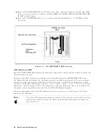
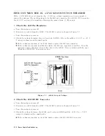
Figure
5-2.
A50
SHUTDO
WN
LED
Location
A50
Shutdown
LED
The
A50
SHUTDOWN
LED
turning
o
indicates
some
of
A50
power
supply
is
shut
down
by
the
A50
shutdown
circuitry
.
There
are
two
F
AN
conditions
,
rotating
and
not
rotating
when
the
SHUTDOWN
LED
turns
o.
When
the
fan
is
rotating,
the
shutdown
circuit
is
probably
activated
by
the
over
current
condition
on
the
power
lines
in
the
A50
DC-DC
Convereter
or
the
A2
P
ost
Regulator
.
In
this
condition,
though
the
A50
power
supplies
,
+24
V
,
+5
VD
,
+18
V
,
+7.8
V
,
-7.8
V
,
and
-18
V
are
shut
down,
the
F
an
P
ower
+24
V
is
still
supplied
to
the
fan.
When
the
fan
is
not
rotating,
the
shutdown
circuit
is
probably
activated
by
the
F
AN
LOCK
signal
missing.
F
or
more
information
about
the
A50
shutdown
circuit
operation,
see
the
Figure
5-12
P
ower
Supply
Block
Diagram
1.
Note
Once
the
A50
shutdown
circuit
is
activated,
the
only
way
to
reset
the
circuit
is
turning
the
analyzer
power
o.
W
ait
a
minute
after
turning
the
analyzer
o.
Then
turn
it
on.
5-4
P
ower
Supply
T
roubleshooting
Содержание Agilent 4396B
Страница 10: ......
Страница 32: ......
Страница 39: ...Figure 2 3 40 MHz Reference Oscillator Frequency Adjustment Location Adjustments and Correction Constants 2 7 ...
Страница 43: ...Figure 2 7 CAL OUT Level Adjustment Location Adjustments and Correction Constants 2 11 ...
Страница 46: ...Figure 2 10 Comb Generator Output 2 14 Adjustments and Correction Constants ...
Страница 54: ...Figure 2 18 Plug Locations 19 Replace the A6 board into the slot 2 22 Adjustments and Correction Constants ...
Страница 62: ...Figure 2 26 Final Gain Adjustment Location 2 30 Adjustments and Correction Constants ...
Страница 70: ...Figure 2 34 IF Gain Errors Correction Constants Setup 2 2 38 Adjustments and Correction Constants ...
Страница 76: ...Figure 3 1 Troubleshooting Organization 3 2 T roubleshooting ...
Страница 84: ......
Страница 90: ...Figure 5 1 Power Supply Lines Simpli ed Block Diagram 5 2 Power Supply T roubleshooting ...
Страница 107: ...Figure 5 12 Power Supply Block Diagram 1 Power Supply T roubleshooting 5 19 ...
Страница 108: ...Figure 5 13 Power Supply Block Diagram 2 5 20 Power Supply T roubleshooting ...
Страница 109: ...Figure 5 14 Power Supply Block Diagram 3 Power Supply T roubleshooting 5 21 ...
Страница 110: ......
Страница 112: ...Figure 6 1 Digital Control Group Simpli ed Block Diagram 6 2 Digital Control T roubleshooting ...
Страница 124: ......
Страница 126: ...Figure 7 1 Source Group Block Diagram 7 2 Source Group T roubleshooting ...
Страница 160: ...Figure 8 1 Receiver Group Simpli ed Block Diagram 8 2 Receiver Group T roubleshooting ...
Страница 168: ......
Страница 184: ...Figure 10 6 External Test Setup 1 Figure 10 7 External Test Setup 2 10 10 Service Key Menus ...
Страница 185: ...Figure 10 8 External Test Setup 3 Figure 10 9 External Test Setup 4 Service Key Menus 10 11 ...
Страница 226: ...Figure 11 3 Power Supply Functional Group Simpli ed Block Diagram 11 6 Theory of Operation ...
Страница 231: ...Figure 11 5 Digital Control Group Simpli ed Block Diagram Theory of Operation 11 11 ...
Страница 235: ...Figure 11 6 Source Simpli ed Block Diagram Theory of Operation 11 15 ...
Страница 244: ...Figure 11 7 Receiver Simpli ed Block Diagram 11 24 Theory of Operation ...
Страница 249: ...Figure IDC5S11001 here Figure 11 8 4396B Source Group Block Diagram Theory of Operation 11 29 ...
Страница 250: ...Figure IDC5S11002 here Figure 11 9 4396B Receiver Group Block Diagram 11 30 Theory of Operation ...
Страница 254: ...Figure 12 1 Top View Major Assemblies 12 4 Replaceable Parts ...
Страница 290: ...Figure 12 36 Main Frame Assembly Parts 17 19 12 40 Replaceable Parts ...
Страница 294: ......
Страница 302: ...Figure B 1 Connector Locations On the A20 Motherboard Circuit Side B 2 A20 Motherboard Pin Assignment ...
Страница 303: ...Figure B 2 Pin Assignment On the A20 Motherboard Circuit Side A20 Motherboard Pin Assignment B 3 ...
Страница 308: ......
Страница 311: ...Figure C 1 Power Cable Supplied Power Requirement C 3 ...
Страница 312: ......
Страница 324: ......


