


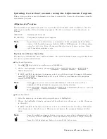


Updating
Correction
Constants
Correction
Constants
are
updated
using
the
following
procedure:
1.
Connect
the
equipment
as
shown
in
Figure
2-1
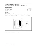
Figure
2-1.
Updating
Correction
Constants
Setup
Note
Steps
2
to
5
are
used
to
select
the
equipment
and
to
set
their
GPIB
addresses
.
When
you
perform
the
A
djustments
Program
the
rst
time
,
perform
these
steps
to
select
the
equipment
and
the
GPIB
address
.
After
that,
perform
the
\TE
A4396B"
program
only
when
you
want
to
change
the
equipment
or
the
GPIB
address
.
2.
Locate
the
Equipment
Conguration
Program
\TE
A4396B"
in
the
address
of
the
drive
or
the
directly
where
the
A
djustment
Program
\ADJ4396B"
will
be
run.
3.
Set
the
mass
storage
unit
specier
(MSUS)
to
the
address
of
the
drive
or
the
directory
where
\TE
A4396B"
is
located.
4.
Load
and
run
\TE
A4396B".
5.
F
ollow
the
instructions
on
the
controller's
screen
until
the
program
ends
.
6.
Set
the
mass
storage
unit
specier
(MSUS)
to
the
address
of
the
drive
or
the
directory
where
the
A
djustment
Program
\ADJ4396B"
is
located.
7.
Load
and
run
\ADJ4396B".
8.
A
window
format
menu
is
displayed.
9.
Choose
\INITIAL
SETUP"
if
you
want
to
update
the
Calibrated
V
alue
for
the
power
sensor
.
10.
Choose
the
item
that
you
want
to
perform.
11.
F
ollow
the
instruction
on
the
controller's
screen
until
the
program
ends
.
The
equipment
connections
are
shown
in
each
Correction
Constants
procedure
in
this
chapter
.
Adjustments
and
Correction
Constants
2-5
Содержание Agilent 4396B
Страница 10: ......
Страница 32: ......
Страница 39: ...Figure 2 3 40 MHz Reference Oscillator Frequency Adjustment Location Adjustments and Correction Constants 2 7 ...
Страница 43: ...Figure 2 7 CAL OUT Level Adjustment Location Adjustments and Correction Constants 2 11 ...
Страница 46: ...Figure 2 10 Comb Generator Output 2 14 Adjustments and Correction Constants ...
Страница 54: ...Figure 2 18 Plug Locations 19 Replace the A6 board into the slot 2 22 Adjustments and Correction Constants ...
Страница 62: ...Figure 2 26 Final Gain Adjustment Location 2 30 Adjustments and Correction Constants ...
Страница 70: ...Figure 2 34 IF Gain Errors Correction Constants Setup 2 2 38 Adjustments and Correction Constants ...
Страница 76: ...Figure 3 1 Troubleshooting Organization 3 2 T roubleshooting ...
Страница 84: ......
Страница 90: ...Figure 5 1 Power Supply Lines Simpli ed Block Diagram 5 2 Power Supply T roubleshooting ...
Страница 107: ...Figure 5 12 Power Supply Block Diagram 1 Power Supply T roubleshooting 5 19 ...
Страница 108: ...Figure 5 13 Power Supply Block Diagram 2 5 20 Power Supply T roubleshooting ...
Страница 109: ...Figure 5 14 Power Supply Block Diagram 3 Power Supply T roubleshooting 5 21 ...
Страница 110: ......
Страница 112: ...Figure 6 1 Digital Control Group Simpli ed Block Diagram 6 2 Digital Control T roubleshooting ...
Страница 124: ......
Страница 126: ...Figure 7 1 Source Group Block Diagram 7 2 Source Group T roubleshooting ...
Страница 160: ...Figure 8 1 Receiver Group Simpli ed Block Diagram 8 2 Receiver Group T roubleshooting ...
Страница 168: ......
Страница 184: ...Figure 10 6 External Test Setup 1 Figure 10 7 External Test Setup 2 10 10 Service Key Menus ...
Страница 185: ...Figure 10 8 External Test Setup 3 Figure 10 9 External Test Setup 4 Service Key Menus 10 11 ...
Страница 226: ...Figure 11 3 Power Supply Functional Group Simpli ed Block Diagram 11 6 Theory of Operation ...
Страница 231: ...Figure 11 5 Digital Control Group Simpli ed Block Diagram Theory of Operation 11 11 ...
Страница 235: ...Figure 11 6 Source Simpli ed Block Diagram Theory of Operation 11 15 ...
Страница 244: ...Figure 11 7 Receiver Simpli ed Block Diagram 11 24 Theory of Operation ...
Страница 249: ...Figure IDC5S11001 here Figure 11 8 4396B Source Group Block Diagram Theory of Operation 11 29 ...
Страница 250: ...Figure IDC5S11002 here Figure 11 9 4396B Receiver Group Block Diagram 11 30 Theory of Operation ...
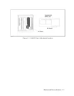
Страница 254: ...Figure 12 1 Top View Major Assemblies 12 4 Replaceable Parts ...
Страница 290: ...Figure 12 36 Main Frame Assembly Parts 17 19 12 40 Replaceable Parts ...
Страница 294: ......
Страница 302: ...Figure B 1 Connector Locations On the A20 Motherboard Circuit Side B 2 A20 Motherboard Pin Assignment ...
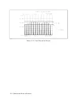
Страница 303: ...Figure B 2 Pin Assignment On the A20 Motherboard Circuit Side A20 Motherboard Pin Assignment B 3 ...
Страница 308: ......
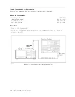
Страница 311: ...Figure C 1 Power Cable Supplied Power Requirement C 3 ...
Страница 312: ......
Страница 324: ......


