


NNNNNNNNNNNNNNNNNNNNNNNNNNNNNNNN
GAIN
X
[
]
(:DIAG:SERV:IF:GAIN:X
{AUTO|DB0|DB18} )
Displays
the
control
menu
for
the
IF
GAIN
X.
The
softkeys
in
this
control
menu
are
described
below
.
The
abbreviation
of
the
current
setting
(A
UTO
,
0
dB
,
or
18
dB)
is
displayed
in
the
brackets
of
the
menu.
NNNNNNNNNNNNNNNNNNNNNNNNNNNNNNNNNNNNNN
GAIN
X:
AUTO
sets
the
IF
GAIN
X
to
automatic
mode
.
NNNNNNNNNNNNNN
0
dB
sets
the
IF
GAIN
X
to
0
dB
.
NNNNNNNNNNNNNNNNN
18
dB
sets
the
IF
GAIN
X
to
18
dB
.
NNNNNNNNNNNNNNNNNNNNNNNNNNNNNNNN
GAIN
Y
[
]
(:DIAG:SERV:IF:GAIN:Y
{AUTO|DB0|DB6|DB12|DB18} )
Displays
the
control
menu
for
the
IF
gain
Y
.
The
softkeys
in
this
control
menu
are
described
below
.
The
abbreviation
of
the
current
setting
(A
UTO
,
0
dB
,
6
dB
,
12
dB
,
or
18
dB)
is
displayed
in
the
brackets
of
the
menu.
NNNNNNNNNNNNNNNNNNNNNNNNNNNNNNNNNNNNNN
GAIN
Y:
AUTO
sets
the
IF
gain
Y
setting
to
automatic
mode
.
NNNNNNNNNNNNNN
0
dB
sets
the
IF
gain
Y
to
0
dB
.
NNNNNNNNNNNNNN
6
dB
sets
the
IF
gain
Y
to
6
dB
.
NNNNNNNNNNNNNNNNN
12
dB
sets
the
IF
gain
Y
to
12
dB
.
NNNNNNNNNNNNNNNNN
18
dB
sets
the
IF
gain
Y
to
18
dB
.
NNNNNNNNNNNNNNNNNNNNNNNNNNNNNNNN
GAIN
Z
[
]
(:DIAG:SERV:IF:GAIN:Z
{AUTO|DB0|DB2|DB4|DB18} )
Displays
the
control
menu
for
the
IF
gain
Z.
The
softkeys
in
this
control
menu
are
described
below
.
The
abbreviation
of
the
current
setting
(A
UTO
,
0
dB
,
2
dB
,
4
dB
,
or
18
dB)
is
displayed
in
the
brackets
of
the
menu.
NNNNNNNNNNNNNNNNNNNNNNNNNNNNNNNNNNNNNN
GAIN
Z:
AUTO
sets
the
IF
GAIN
Z
setting
to
automatic
mode
.
N
NNNNNNNNNNNNN
0
dB
sets
the
IF
GAIN
Z
to
0
dB
.
NNNNNNNNNNNNNN
2
dB
sets
the
IF
GAIN
Z
to
2
dB
.
NNNNNNNNNNNNNN
4
dB
sets
the
IF
GAIN
Z
to
4
dB
.
NNNNNNNNNNNNNNNNN
18
dB
sets
the
IF
GAIN
Z
to
18
dB
.
W
WWWWWWWWWWWWWWWWWWWWWWWWWWWWWWWWWWWWWWWWWWWWWWWWW
IF
RANGE
[
]
Displays
the
control
menus
that
allow
you
to
control
the
IF
ranges
F
and
R
in
the
A6
receiver
IF
.
The
softkeys
in
these
control
menus
are
described
below
.
The
abbreviation
of
the
current
setting
(A
UTO
or
MANU
AL)
is
displayed
in
the
brackets
of
the
menu.
NNNNNNNNNNNNNNNNNNNNNNNNNNNNNNNNNNNNNNNNNNNNNNNNNNNNN
IF
RANGE
AUTO
man
(:DIAG:SERV:IF:RANG:MODE
{AUTO|MAN} )
T
oggles
the
IF
range
control
mode
to
automatic
mode
(normal
operation)
or
manual
mode
.
In
the
automatic
mode
,
the
analyzer
controls
the
IF
range
F
and
R
settings
automatically
according
to
the
measurement
setting.
In
the
manual
mode
,
the
IF
ranges
are
controlled
by
the
following
softkeys
.
Service
K
ey
Menus
10-37
Содержание Agilent 4396B
Страница 10: ......
Страница 32: ......
Страница 39: ...Figure 2 3 40 MHz Reference Oscillator Frequency Adjustment Location Adjustments and Correction Constants 2 7 ...
Страница 43: ...Figure 2 7 CAL OUT Level Adjustment Location Adjustments and Correction Constants 2 11 ...
Страница 46: ...Figure 2 10 Comb Generator Output 2 14 Adjustments and Correction Constants ...
Страница 54: ...Figure 2 18 Plug Locations 19 Replace the A6 board into the slot 2 22 Adjustments and Correction Constants ...
Страница 62: ...Figure 2 26 Final Gain Adjustment Location 2 30 Adjustments and Correction Constants ...
Страница 70: ...Figure 2 34 IF Gain Errors Correction Constants Setup 2 2 38 Adjustments and Correction Constants ...
Страница 76: ...Figure 3 1 Troubleshooting Organization 3 2 T roubleshooting ...
Страница 84: ......
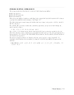
Страница 90: ...Figure 5 1 Power Supply Lines Simpli ed Block Diagram 5 2 Power Supply T roubleshooting ...
Страница 107: ...Figure 5 12 Power Supply Block Diagram 1 Power Supply T roubleshooting 5 19 ...
Страница 108: ...Figure 5 13 Power Supply Block Diagram 2 5 20 Power Supply T roubleshooting ...
Страница 109: ...Figure 5 14 Power Supply Block Diagram 3 Power Supply T roubleshooting 5 21 ...
Страница 110: ......
Страница 112: ...Figure 6 1 Digital Control Group Simpli ed Block Diagram 6 2 Digital Control T roubleshooting ...
Страница 124: ......
Страница 126: ...Figure 7 1 Source Group Block Diagram 7 2 Source Group T roubleshooting ...
Страница 160: ...Figure 8 1 Receiver Group Simpli ed Block Diagram 8 2 Receiver Group T roubleshooting ...
Страница 168: ......
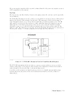
Страница 184: ...Figure 10 6 External Test Setup 1 Figure 10 7 External Test Setup 2 10 10 Service Key Menus ...
Страница 185: ...Figure 10 8 External Test Setup 3 Figure 10 9 External Test Setup 4 Service Key Menus 10 11 ...
Страница 226: ...Figure 11 3 Power Supply Functional Group Simpli ed Block Diagram 11 6 Theory of Operation ...
Страница 231: ...Figure 11 5 Digital Control Group Simpli ed Block Diagram Theory of Operation 11 11 ...
Страница 235: ...Figure 11 6 Source Simpli ed Block Diagram Theory of Operation 11 15 ...
Страница 244: ...Figure 11 7 Receiver Simpli ed Block Diagram 11 24 Theory of Operation ...
Страница 249: ...Figure IDC5S11001 here Figure 11 8 4396B Source Group Block Diagram Theory of Operation 11 29 ...
Страница 250: ...Figure IDC5S11002 here Figure 11 9 4396B Receiver Group Block Diagram 11 30 Theory of Operation ...
Страница 254: ...Figure 12 1 Top View Major Assemblies 12 4 Replaceable Parts ...
Страница 290: ...Figure 12 36 Main Frame Assembly Parts 17 19 12 40 Replaceable Parts ...
Страница 294: ......
Страница 302: ...Figure B 1 Connector Locations On the A20 Motherboard Circuit Side B 2 A20 Motherboard Pin Assignment ...
Страница 303: ...Figure B 2 Pin Assignment On the A20 Motherboard Circuit Side A20 Motherboard Pin Assignment B 3 ...
Страница 308: ......
Страница 311: ...Figure C 1 Power Cable Supplied Power Requirement C 3 ...
Страница 312: ......
Страница 324: ......


