


2
A
djustments
and
Correction
Constants
Introduction
This
chapter
describes
the
A
djustments
and
Correction
Constants
procedures
required
to
ensure
that
the
4396B
Network/Spectrum/Impedance
Analyzer
is
within
its
specications
.
These
adjustments
should
be
performed
along
with
periodic
maintenance
to
keep
the
analyzer
in
optimum
operating
condition.
The
recommended
calibration
period
is
12
months
.
If
proper
performance
cannot
be
achieved
after
the
A
djustments
and
Correction
Constants
procedures
are
performed,
see
Chapter
3.
Note
The
correction
constants
are
empirically
derived
data
that
is
stored
in
memory
and
then
recalled
to
rene
the
analyzer's
measurement
and
to
dene
its
operation.
Safety
Considerations
This
manual
contains
NOTEs
,
CA
UTIONs
,
and
W
ARNINGs
that
must
be
followed
to
ensure
the
safety
of
the
operator
and
to
keep
the
instrument
in
a
safe
and
serviceable
condition.
The
adjustments
must
be
performed
by
qualied
service
personnel.
W
arning
Any
interruption
of
the
protective
ground
conductor
(inside
or
outside
the
analyzer)
or
disconnection
of
the
protective
ground
terminal
can
make
the
instrument
dangerous
.
Intentional
interruption
of
the
protective
ground
system
for
any
reason
is
prohibited.
The
removal
or
opening
of
covers
for
adjustment,
or
removal
of
parts
other
than
those
that
are
accessible
by
hand
will
expose
circuits
containing
dangerous
voltage
levels
.
Remember
that
the
capacitors
in
the
analyzer
can
remain
charged
for
several
minutes
,
even
through
you
have
turned
the
analyzer
OFF
and
unplugged
it.
W
arning
The
adjustments
described
in
this
chapter
are
performed
with
power
applied
and
the
protective
covers
removed.
Dangerous
voltage
levels
exist
at
many
points
and
can
result
in
serious
personal
injury
or
death
if
you
come
into
contact
with
them.
Adjustments
and
Correction
Constants
2-1
Содержание Agilent 4396B
Страница 10: ......
Страница 32: ......
Страница 39: ...Figure 2 3 40 MHz Reference Oscillator Frequency Adjustment Location Adjustments and Correction Constants 2 7 ...
Страница 43: ...Figure 2 7 CAL OUT Level Adjustment Location Adjustments and Correction Constants 2 11 ...
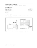
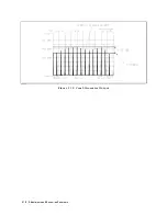
Страница 46: ...Figure 2 10 Comb Generator Output 2 14 Adjustments and Correction Constants ...
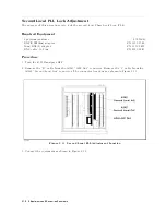
Страница 54: ...Figure 2 18 Plug Locations 19 Replace the A6 board into the slot 2 22 Adjustments and Correction Constants ...
Страница 62: ...Figure 2 26 Final Gain Adjustment Location 2 30 Adjustments and Correction Constants ...
Страница 70: ...Figure 2 34 IF Gain Errors Correction Constants Setup 2 2 38 Adjustments and Correction Constants ...
Страница 76: ...Figure 3 1 Troubleshooting Organization 3 2 T roubleshooting ...
Страница 84: ......
Страница 90: ...Figure 5 1 Power Supply Lines Simpli ed Block Diagram 5 2 Power Supply T roubleshooting ...
Страница 107: ...Figure 5 12 Power Supply Block Diagram 1 Power Supply T roubleshooting 5 19 ...
Страница 108: ...Figure 5 13 Power Supply Block Diagram 2 5 20 Power Supply T roubleshooting ...
Страница 109: ...Figure 5 14 Power Supply Block Diagram 3 Power Supply T roubleshooting 5 21 ...
Страница 110: ......
Страница 112: ...Figure 6 1 Digital Control Group Simpli ed Block Diagram 6 2 Digital Control T roubleshooting ...
Страница 124: ......
Страница 126: ...Figure 7 1 Source Group Block Diagram 7 2 Source Group T roubleshooting ...
Страница 160: ...Figure 8 1 Receiver Group Simpli ed Block Diagram 8 2 Receiver Group T roubleshooting ...
Страница 168: ......
Страница 184: ...Figure 10 6 External Test Setup 1 Figure 10 7 External Test Setup 2 10 10 Service Key Menus ...
Страница 185: ...Figure 10 8 External Test Setup 3 Figure 10 9 External Test Setup 4 Service Key Menus 10 11 ...
Страница 226: ...Figure 11 3 Power Supply Functional Group Simpli ed Block Diagram 11 6 Theory of Operation ...
Страница 231: ...Figure 11 5 Digital Control Group Simpli ed Block Diagram Theory of Operation 11 11 ...
Страница 235: ...Figure 11 6 Source Simpli ed Block Diagram Theory of Operation 11 15 ...
Страница 244: ...Figure 11 7 Receiver Simpli ed Block Diagram 11 24 Theory of Operation ...
Страница 249: ...Figure IDC5S11001 here Figure 11 8 4396B Source Group Block Diagram Theory of Operation 11 29 ...
Страница 250: ...Figure IDC5S11002 here Figure 11 9 4396B Receiver Group Block Diagram 11 30 Theory of Operation ...
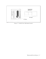
Страница 254: ...Figure 12 1 Top View Major Assemblies 12 4 Replaceable Parts ...
Страница 290: ...Figure 12 36 Main Frame Assembly Parts 17 19 12 40 Replaceable Parts ...
Страница 294: ......
Страница 302: ...Figure B 1 Connector Locations On the A20 Motherboard Circuit Side B 2 A20 Motherboard Pin Assignment ...
Страница 303: ...Figure B 2 Pin Assignment On the A20 Motherboard Circuit Side A20 Motherboard Pin Assignment B 3 ...
Страница 308: ......
Страница 311: ...Figure C 1 Power Cable Supplied Power Requirement C 3 ...
Страница 312: ......
Страница 324: ......


