


Updating
Correction
Constants
using
the
A
djustments
Program
This
section
provides
general
information
on
how
to
update
the
Correction
Constants
using
the
adjustments
program.
A
djustments
Program
The
adjustments
program
is
provided
on
one
double-sided
diskette
.
Refer
to
T
able
1-1
for
the
Agilent
part
number
of
the
adjustement
program.
The
les
contained
on
the
diskette
are
as
follows:
ADJ4396B
A
djustments
Program
TE
A4396B
Equipment
Conguration
Program
Note
T
o
prevent
accidental
deletion
or
destruction
of
the
program,
make
working
copies
of
the
furnished
master
diskette
(HFS
or
SRM
system).
Use
the
working
copies
for
daily
use
.
Keep
the
master
diskettes
in
a
safe
place
and
use
them
only
for
making
working
copies
.
K
eyboard
and
Mouse
Operation
The
menus
in
\ADJ4396B"
use
a
window
format.
The
window
format
menu
supports
keyboard
and
mouse
operations
as
follows:
Keyboard
Operation
1.
Press
4
8
5 ,
4
9
5
keys
until
your
preference
is
highlighted.
2.
Choose
the
highlighted
item
by
pressing
4
RETURN
5
or
4
SELECT
5
(4
ENTER
5
or
4
EXECUTE
5 ,
if
Nimitz
Keyboard).
3.
If
NNNNNNNNNNNNNN
QUIT
or
NNNNNNNNNNNNNN
EXIT
is
displayed
in
a
menu,
select
one
of
these
to
exit
the
menu.
Otherwise
,
press
4
5
(4
CONTINUE
5 ,
if
Nimitz
Keyboard)
to
exit.
When
you
exit
menus
,
the
program
displays
another
menu.
Note
Press
4
?
5
to
access
on-screen
help
information
for
the
selection
you
have
highlighted.
Help
information
appears
in
a
display
window
.
Press
4
RETURN
5
or
4
SELECT
5
(4
ENTER
5
or
4
EXECUTE
5 ,
if
Nimitz
Keyboard)
to
turn
o
the
help
screen.
Mouse
Operation
1.
Slide
the
mouse
up
or
down
until
your
preference
is
highlighted.
2.
Choose
the
highlighted
item
by
pressing
left-hand
button
on
the
mouse
,
or
slide
the
mouse
to
the
right.
3.
If
NNNNNNNNNNNNNN
QUIT
or
NNNNNNNNNNNNNN
EXIT
is
displayed
in
a
menu,
select
one
of
these
to
exit
the
menu.
Otherwise
,
slide
the
mouse
to
the
left
to
exit.
When
you
exit
menus
,
the
program
displays
another
menu.
Note
Press
the
right-hand
mouse
button
to
access
on-screen
help
information
for
the
selection
you
have
highlighted.
Help
information
appears
in
a
display
window
.
Press
the
left-hand
mouse
button
to
turn
o
the
help
screen.
Adjustments
and
Correction
Constants
2-3
Содержание Agilent 4396B
Страница 10: ......
Страница 32: ......
Страница 39: ...Figure 2 3 40 MHz Reference Oscillator Frequency Adjustment Location Adjustments and Correction Constants 2 7 ...
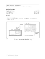
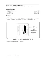
Страница 43: ...Figure 2 7 CAL OUT Level Adjustment Location Adjustments and Correction Constants 2 11 ...
Страница 46: ...Figure 2 10 Comb Generator Output 2 14 Adjustments and Correction Constants ...
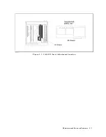
Страница 54: ...Figure 2 18 Plug Locations 19 Replace the A6 board into the slot 2 22 Adjustments and Correction Constants ...
Страница 62: ...Figure 2 26 Final Gain Adjustment Location 2 30 Adjustments and Correction Constants ...
Страница 70: ...Figure 2 34 IF Gain Errors Correction Constants Setup 2 2 38 Adjustments and Correction Constants ...
Страница 76: ...Figure 3 1 Troubleshooting Organization 3 2 T roubleshooting ...
Страница 84: ......
Страница 90: ...Figure 5 1 Power Supply Lines Simpli ed Block Diagram 5 2 Power Supply T roubleshooting ...
Страница 107: ...Figure 5 12 Power Supply Block Diagram 1 Power Supply T roubleshooting 5 19 ...
Страница 108: ...Figure 5 13 Power Supply Block Diagram 2 5 20 Power Supply T roubleshooting ...
Страница 109: ...Figure 5 14 Power Supply Block Diagram 3 Power Supply T roubleshooting 5 21 ...
Страница 110: ......
Страница 112: ...Figure 6 1 Digital Control Group Simpli ed Block Diagram 6 2 Digital Control T roubleshooting ...
Страница 124: ......
Страница 126: ...Figure 7 1 Source Group Block Diagram 7 2 Source Group T roubleshooting ...
Страница 160: ...Figure 8 1 Receiver Group Simpli ed Block Diagram 8 2 Receiver Group T roubleshooting ...
Страница 168: ......
Страница 184: ...Figure 10 6 External Test Setup 1 Figure 10 7 External Test Setup 2 10 10 Service Key Menus ...
Страница 185: ...Figure 10 8 External Test Setup 3 Figure 10 9 External Test Setup 4 Service Key Menus 10 11 ...
Страница 226: ...Figure 11 3 Power Supply Functional Group Simpli ed Block Diagram 11 6 Theory of Operation ...
Страница 231: ...Figure 11 5 Digital Control Group Simpli ed Block Diagram Theory of Operation 11 11 ...
Страница 235: ...Figure 11 6 Source Simpli ed Block Diagram Theory of Operation 11 15 ...
Страница 244: ...Figure 11 7 Receiver Simpli ed Block Diagram 11 24 Theory of Operation ...
Страница 249: ...Figure IDC5S11001 here Figure 11 8 4396B Source Group Block Diagram Theory of Operation 11 29 ...
Страница 250: ...Figure IDC5S11002 here Figure 11 9 4396B Receiver Group Block Diagram 11 30 Theory of Operation ...
Страница 254: ...Figure 12 1 Top View Major Assemblies 12 4 Replaceable Parts ...
Страница 290: ...Figure 12 36 Main Frame Assembly Parts 17 19 12 40 Replaceable Parts ...
Страница 294: ......
Страница 302: ...Figure B 1 Connector Locations On the A20 Motherboard Circuit Side B 2 A20 Motherboard Pin Assignment ...
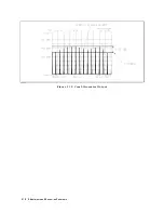
Страница 303: ...Figure B 2 Pin Assignment On the A20 Motherboard Circuit Side A20 Motherboard Pin Assignment B 3 ...
Страница 308: ......
Страница 311: ...Figure C 1 Power Cable Supplied Power Requirement C 3 ...
Страница 312: ......
Страница 324: ......


