


A
Manual
Changes
Introduction
This
appendix
contains
the
information
required
to
adapt
this
manual
to
earlier
versions
or
congurations
of
the
analyzer
than
the
current
printing
date
of
this
manual.
The
information
in
this
manual
applies
directly
to
the
4396B
Network/Spectrum
Analyzer
serial
number
prex
listed
on
the
title
page
of
this
manual.
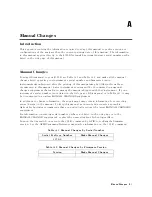
Manual
Changes
T
o
adapt
this
manual
to
your
4396B,
see
T
able
A
-1
and
T
able
A
-2,
and
make
all
the
manual
changes
listed
opposite
your
instrument's
serial
number
and
rmware
version.
Instruments
manufactured
after
the
printing
of
this
manual
may
be
dierent
from
those
documented
in
this
manual.
Later
instrument
versions
will
be
documented
in
a
manual
changes
supplement
that
will
accompany
the
manual
shipped
with
that
instrument.
If
your
instrument's
serial
number
is
not
listed
on
the
title
page
of
this
manual
or
in
T
able
A
-1 ,
it
may
be
documented
in
a
yellow
MANU
AL
CHANGES
supplement.
In
additions
to
change
information,
the
supplement
may
contain
information
for
correcting
errors
(Errata)
in
the
manual.
T
o
keep
this
manual
as
current
and
accurate
as
possible
,
Agilent
T
echnologies
recommends
that
you
periodically
request
the
latest
MANU
AL
CHANGES
supplement.
F
or
information
concerning
serial
number
prexes
not
listed
on
the
title
page
or
in
the
MANU
AL
CHANGE
supplement,
contact
the
nearest
Agilent
T
echnologies
oce
.
Turn
on
the
line
switch
or
execute
the
*IDN?
command
by
GPIB
to
conrm
the
rmware
version.
See
the
GPIB
Command
R
eference
manual
for
information
on
the
*IDN?
command.
T
able
A
-1.
Manual
Changes
by
Serial
Number
Serial
Prex
or
Number
Make
Manual
Changes
JP1KE
T
able
A
-2.
Manual
Changes
by
Firmware
V
ersion
V
ersion
Make
Manual
Changes
Manual
Changes
A-1
Содержание Agilent 4396B
Страница 10: ......
Страница 32: ......
Страница 39: ...Figure 2 3 40 MHz Reference Oscillator Frequency Adjustment Location Adjustments and Correction Constants 2 7 ...
Страница 43: ...Figure 2 7 CAL OUT Level Adjustment Location Adjustments and Correction Constants 2 11 ...
Страница 46: ...Figure 2 10 Comb Generator Output 2 14 Adjustments and Correction Constants ...
Страница 54: ...Figure 2 18 Plug Locations 19 Replace the A6 board into the slot 2 22 Adjustments and Correction Constants ...
Страница 62: ...Figure 2 26 Final Gain Adjustment Location 2 30 Adjustments and Correction Constants ...
Страница 70: ...Figure 2 34 IF Gain Errors Correction Constants Setup 2 2 38 Adjustments and Correction Constants ...
Страница 76: ...Figure 3 1 Troubleshooting Organization 3 2 T roubleshooting ...
Страница 84: ......
Страница 90: ...Figure 5 1 Power Supply Lines Simpli ed Block Diagram 5 2 Power Supply T roubleshooting ...
Страница 107: ...Figure 5 12 Power Supply Block Diagram 1 Power Supply T roubleshooting 5 19 ...
Страница 108: ...Figure 5 13 Power Supply Block Diagram 2 5 20 Power Supply T roubleshooting ...
Страница 109: ...Figure 5 14 Power Supply Block Diagram 3 Power Supply T roubleshooting 5 21 ...
Страница 110: ......
Страница 112: ...Figure 6 1 Digital Control Group Simpli ed Block Diagram 6 2 Digital Control T roubleshooting ...
Страница 124: ......
Страница 126: ...Figure 7 1 Source Group Block Diagram 7 2 Source Group T roubleshooting ...
Страница 160: ...Figure 8 1 Receiver Group Simpli ed Block Diagram 8 2 Receiver Group T roubleshooting ...
Страница 168: ......
Страница 184: ...Figure 10 6 External Test Setup 1 Figure 10 7 External Test Setup 2 10 10 Service Key Menus ...
Страница 185: ...Figure 10 8 External Test Setup 3 Figure 10 9 External Test Setup 4 Service Key Menus 10 11 ...
Страница 226: ...Figure 11 3 Power Supply Functional Group Simpli ed Block Diagram 11 6 Theory of Operation ...
Страница 231: ...Figure 11 5 Digital Control Group Simpli ed Block Diagram Theory of Operation 11 11 ...
Страница 235: ...Figure 11 6 Source Simpli ed Block Diagram Theory of Operation 11 15 ...
Страница 244: ...Figure 11 7 Receiver Simpli ed Block Diagram 11 24 Theory of Operation ...
Страница 249: ...Figure IDC5S11001 here Figure 11 8 4396B Source Group Block Diagram Theory of Operation 11 29 ...
Страница 250: ...Figure IDC5S11002 here Figure 11 9 4396B Receiver Group Block Diagram 11 30 Theory of Operation ...
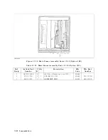
Страница 254: ...Figure 12 1 Top View Major Assemblies 12 4 Replaceable Parts ...
Страница 290: ...Figure 12 36 Main Frame Assembly Parts 17 19 12 40 Replaceable Parts ...
Страница 294: ......
Страница 302: ...Figure B 1 Connector Locations On the A20 Motherboard Circuit Side B 2 A20 Motherboard Pin Assignment ...
Страница 303: ...Figure B 2 Pin Assignment On the A20 Motherboard Circuit Side A20 Motherboard Pin Assignment B 3 ...
Страница 308: ......
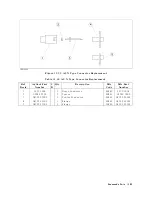
Страница 311: ...Figure C 1 Power Cable Supplied Power Requirement C 3 ...
Страница 312: ......
Страница 324: ......


