Dangerous
Procedure
W
arnings
W
arnings
,
such
as
the
example
below
,
precede
potentially
dangerous
procedures
throughout
this
manual.
Instructions
contained
in
the
warnings
must
be
followed.
W
arning
Dangerous
voltages
,
capable
of
causing
death,
are
present
in
this
instrument.
Use
extreme
caution
when
handling,
testing,
and
adjusting
this
instrument.
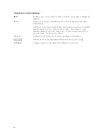
Safety
Symbols
General
denitions
of
safety
symbols
used
on
equipment
or
in
manuals
are
listed
below
.
Instruction
manual
symbol:
the
product
is
marked
with
this
symbol
when
it
is
necessary
for
the
user
to
refer
to
the
instruction
manual.
Alternating
current.
Direct
current.
On
(Supply).
O
(Supply).
In
position
of
push-button
switch.
Out
position
of
push-button
switch.
Frame
(or
chassis)
terminal.
A
connection
to
the
frame
(chassis)
of
the
equipment
which
normally
include
all
exposed
metal
structures
.
This
W
arning
sign
denotes
a
hazard.
It
calls
attention
to
a
procedure
,
practice
,
condition
or
the
like
,
which,
if
not
correctly
performed
or
adhered
to
,
could
result
in
injury
or
death
to
personnel.
This
Caution
sign
denotes
a
hazard.
It
calls
attention
to
a
procedure
,
practice
,
condition
or
the
like
,
which,
if
not
correctly
performed
or
adhered
to
,
could
result
in
damage
to
or
destruction
of
part
or
all
of
the
product.
This
Note
sigh
denotes
important
information.
It
calls
attention
to
a
procedure
,
practice
,
condition
or
the
like
,
which
is
essential
to
highlight.
Axed
to
product
containing
static
sensitive
devices
use
anti-static
handling
procedures
to
prevent
electrostatic
discharge
damage
to
component.
v
Содержание Agilent 4396B
Страница 10: ......
Страница 32: ......
Страница 39: ...Figure 2 3 40 MHz Reference Oscillator Frequency Adjustment Location Adjustments and Correction Constants 2 7 ...
Страница 43: ...Figure 2 7 CAL OUT Level Adjustment Location Adjustments and Correction Constants 2 11 ...
Страница 46: ...Figure 2 10 Comb Generator Output 2 14 Adjustments and Correction Constants ...
Страница 54: ...Figure 2 18 Plug Locations 19 Replace the A6 board into the slot 2 22 Adjustments and Correction Constants ...
Страница 62: ...Figure 2 26 Final Gain Adjustment Location 2 30 Adjustments and Correction Constants ...
Страница 70: ...Figure 2 34 IF Gain Errors Correction Constants Setup 2 2 38 Adjustments and Correction Constants ...
Страница 76: ...Figure 3 1 Troubleshooting Organization 3 2 T roubleshooting ...
Страница 84: ......
Страница 90: ...Figure 5 1 Power Supply Lines Simpli ed Block Diagram 5 2 Power Supply T roubleshooting ...
Страница 107: ...Figure 5 12 Power Supply Block Diagram 1 Power Supply T roubleshooting 5 19 ...
Страница 108: ...Figure 5 13 Power Supply Block Diagram 2 5 20 Power Supply T roubleshooting ...
Страница 109: ...Figure 5 14 Power Supply Block Diagram 3 Power Supply T roubleshooting 5 21 ...
Страница 110: ......
Страница 112: ...Figure 6 1 Digital Control Group Simpli ed Block Diagram 6 2 Digital Control T roubleshooting ...
Страница 124: ......
Страница 126: ...Figure 7 1 Source Group Block Diagram 7 2 Source Group T roubleshooting ...
Страница 160: ...Figure 8 1 Receiver Group Simpli ed Block Diagram 8 2 Receiver Group T roubleshooting ...
Страница 168: ......
Страница 184: ...Figure 10 6 External Test Setup 1 Figure 10 7 External Test Setup 2 10 10 Service Key Menus ...
Страница 185: ...Figure 10 8 External Test Setup 3 Figure 10 9 External Test Setup 4 Service Key Menus 10 11 ...
Страница 226: ...Figure 11 3 Power Supply Functional Group Simpli ed Block Diagram 11 6 Theory of Operation ...
Страница 231: ...Figure 11 5 Digital Control Group Simpli ed Block Diagram Theory of Operation 11 11 ...
Страница 235: ...Figure 11 6 Source Simpli ed Block Diagram Theory of Operation 11 15 ...
Страница 244: ...Figure 11 7 Receiver Simpli ed Block Diagram 11 24 Theory of Operation ...
Страница 249: ...Figure IDC5S11001 here Figure 11 8 4396B Source Group Block Diagram Theory of Operation 11 29 ...
Страница 250: ...Figure IDC5S11002 here Figure 11 9 4396B Receiver Group Block Diagram 11 30 Theory of Operation ...
Страница 254: ...Figure 12 1 Top View Major Assemblies 12 4 Replaceable Parts ...
Страница 290: ...Figure 12 36 Main Frame Assembly Parts 17 19 12 40 Replaceable Parts ...
Страница 294: ......
Страница 302: ...Figure B 1 Connector Locations On the A20 Motherboard Circuit Side B 2 A20 Motherboard Pin Assignment ...
Страница 303: ...Figure B 2 Pin Assignment On the A20 Motherboard Circuit Side A20 Motherboard Pin Assignment B 3 ...
Страница 308: ......
Страница 311: ...Figure C 1 Power Cable Supplied Power Requirement C 3 ...
Страница 312: ......
Страница 324: ......


